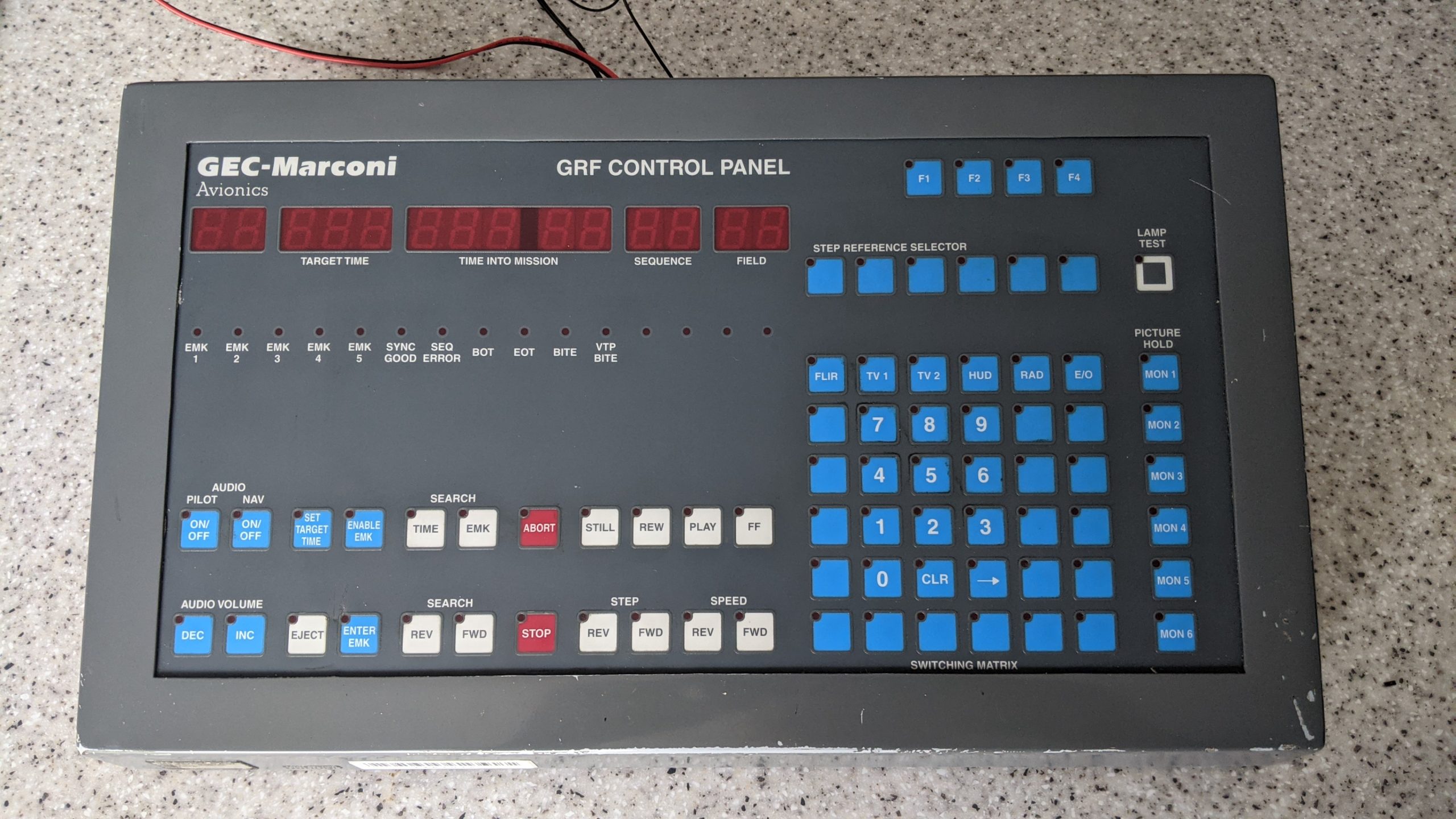
20V 1.5A bench PSU with ATtiny85 based electronic fuse

I built a bench power supply for a relative which had to be low cost and I decided to use Bangood as my source of most of the parts to reduce cost. I purchased the case, relay module, DC-DC converter board, panel meter and the output banana jacks from Bangood and the rest came from my spares box. I had a number of issues with these cheap parts as they didn’t work as intended or simply just didn’t work. But more on that later.

The XL4016 based switch mode DC-DC converter board only allowed you to adjust the voltage output and it did not have a current limiter on it. The module is rated at 8 amps output but the tiny heatsinks suggest that it’s probably half that and the transformer feeding it is only rated at 2 amps max. I did a review of the XL4016E1 DC-DC converter module separately; see this link for the first impressions and the flaws I found with it.

This has yet to have the dymo labels fitted and is being load tested.

So I decided to make an auto cutout circuit that works by monitoring the current via an ACS712-5A sensor. The ATtiny85 switches the PSU load on and off via a push button toggle. Useful as the module I’ve used does not have remote off / on facility and it’s handy to turn the output off whilst connecting up your projects rather than having it permanently on. When the output is on the sensor is read and if the current goes above 1.75 amps the output is disconnected and a red LED lights. A green LED indicates that the output is on and all is OK. I used a dual colour LED that simply turns red or green depending on condition. Originally I was going to measure temperature of the XL4016 module too using an LM35 but there were not enough pins on the ATtiny85 and the switching noise from the module produced erratic analog readings that I could not fully filter out. This didn’t present a problem with current sensing however.

Continue reading →

DSN-VC288 voltmeter and current meter review (in short they are shite)

I bought one of the commonly available dual display panel meters with the part number DSN-VC288 which has three digits and shows voltage to 1 decimal place and current to 2 decimal places. It can measure 0-99.9V and 0-10A and features a red display for the voltage and blue for the current. There seems to be several versions of these panel meters; some with 4 digits and some with three. Some of the three digit ones appear to have auto ranging showing voltage to 2 decimal places if less than 10V however mine does not have this facility.

They look smart enough but as everything that is cheap & made in China, they don’t work as intended, are unreliable, poor quality and cannot be used for anything were accuracy is required. There are two ways of connecting these depending on if the supply voltage is different to the voltage being measured or if the meter gets it’s power from the same source it is measuring. In my case I used a seperate supply as the meter stops working below 4V. I definitely did connect it up correctly and have done a bit of research into these.

DSC-VC288 piece of crap voltmeter.

The problems I had was simply the accuracy is way off. It is advertised as 0.1% accuracy for voltage and 1% for current however this definitely isn’t the case. Out of the box, a 5.0V reference voltage measured on a calibrated DVM showed 5.3V and a 20V reference showed 21.8V. On the rear there is a little trimpot so I managed to adjust this to get a reasonable result and now 5V reads 5.0V but 20V reads 20.5V so if this thing can measure up to 100V then the scale appears to be non linear and it is impossible to get an accurate reading throughout the range. I fiddled with it for ages and the accuracy is just unacceptable. In the end I used it to measure voltages up to 20V with emphasis on accuracy being at the bottom end of the scale.

Now as for the current this is a different story. I found that this was showing 0.67A with a 0.5A load and 2.3A with a 2.0A load and the adjustment trimmer was already at the minimum value. The meter does read zero when no current is flowing so the reset trick I found on the web did not work. I also found that some of the component values on the board differ to photos and a schematic I found implying incorrect value components have been fitted.

Continue reading →

Bangood XL4016 adjustable voltage regulator first impressions

I am building a basic power supply for a project and decided to try one of the XL4016E1 based regulator modules commonly available on eBay, Amazon and Bangood which is advertised as being able to handle an 8A / 200W load. I only need up to 2A for my project but at £7.99 it seemed like a bargain and much cheaper than building my own regulator. The one I bought looks like this:-

I bench tested the unit with an input voltage of 30V (the board can handle up to 40V) and subjected it to various loads most of which it handled well. The major issue with this regulator is that it is almost impossible to set the output voltage accurately as the potentiometer is only single turn and the slightest touch makes the voltage jump around. It is very sensitive particularly at the bottom end of the scale e.g if you are wanting to set it to 5.00V then this is almost impossible but say 26.55V then this is easier although it is still difficult. I replaced the potentiometer / switch assembly with a 50K multi turn pot and bridged out the switch pins. The photo below shows the modification I made. The fitted potentiometer was difficult to remove and I inadvertently pulled out some of the board’s through hole plating and tore a PCB trace. I managed to fix this and the board works fine. However even with a 10 turn pot trying to set an exact output voltage to within 10mV was still difficult at the bottom end of the scale.

Continue reading →

Convert cordless drill to lithium battery using RC lipo

Surprisingly even now you can still buy power tools that come with NiCad batteries (not even NiMh) which are a poor choice of battery for power tools due to their memory effect and high self discharge rate. NiMh is a better choice of battery to use but I presume NiMh is cheaper hence why some tools still come with them. I have a bosch drill and hedge trimmer that both use the same type of 14.4V battery which have failed, even the spare one and a cheap Chinese knock off that was bought as a spare. This is simply because they don’t get used often and the batteries self discharge when left in the garage. Upon opening the batteries and checking the cells some of them measured zero volts and were short circuit both in the genuine batteries and the knock off clone battery. Many had leaked too.

Completed bosch drill lithium battery conversion

The internal cells are around the same size of a C size battery but replacing them with NiMH C cells was out of the question as they would not physically fit into the battery casing. As I had a universal RC charger I opted for lipo batteries and charge them using the balance charger but went without the protection board for the low voltage cutoff. This could potentially be a bad idea but I fitted a small bar graph indicator into the battery pack for monitoring the battery voltage. A push button switch connects the indicator across the battery so it does not drain the battery when in storage.

To convert cordless power tools to lithium the correct way would be to use 18650 cells and a proper BMS board as many others have done. This was my original plan but RC lipo battery packs are better suited to high current discharge rates (many 18650 cells are not, the exception being the ones designed for e-cigarettes) and can handle sudden high current spikes. They can also be charged rapidly too. Using cells from old laptop batteries is not a good idea as some will be in better condition than others leading to cell voltages being out of balance. Also they are not designed for high current discharge rates; larger tools may take 20 amps when the chuck is stalled. It’s always best to use brand new cells and a good BMS board. It’s also worth mentioning that if a BMS board is used you must make sure there is back emf protection inside the drill otherwise this will destroy the BMS board when the motor switches off. If the tool does not have such protection across the motor then a small non polarised capacitor of around 10uf should be fitted across the motor. A high power diode in reverse across the battery (after the switch / trigger) should be fitted too. If this is placed across the motor it would be forward biased when the drill is in reverse. This is assuming the drill simply reverses the motor polarity to change rotation direction. I’ve seen several bad reviews for BMS protection boards purchased on ebay / Amazon saying they failed when used for power tool conversion and the lack of the diode and capacitor is almost certainly why they failed.

Here’s some photos of what I did. It’s nothing too fancy as there’s no BMS board or spot welding to do here:-

Continue reading →

Using Arduino to control display module salvaged from LED sign.

I came across someone selling parts from a large LED sign on ebay which by doing some research came from a Data Display LED board originally used for movie name, showtimes and price information display in a cinema lobby. Their part number could be DL110 as that’s the only number I can find on the board. The module I got consists of 12 5×7 LED matrix modules with the shift registers and row driver circuitry so it can be directly interfaced to a microcontroller. Looking at the date codes on the IC’s this thing dates from 1997 / 1998 so is over 20 years old and certainly not something you can buy anymore. Even then it would be a custom part. This was really bought for something to mess around with whilst in lockdown and I do have a possible use for it as a sign to put in the rear window of a car to inform other road users of their driving skills (or lack of)… don’t hog the middle lane you dumbass lol. 🙂

I obviously didn’t have a datasheet but reverse engineering the module by obtaining datasheets for the chips used on the module was fairly easy. The data comes in via a 14 pin connector and goes through buffers then to the row and column drivers. There is another connector for daisy chaining to the next module. I found that the 7 row drive signals come in then go through a 74HC373 latch which was being used as a buffer as it’s relevant enable pins where permanently tied high / low as required. The output enable / latch, clock and data are buffered by AND gates with the two AND inputs tied together. Seems strange how they did this as a schmitt trigger would have sufficed instead. The row drive signals then go on to a mosfet / power transistor driver chip and then finally to the row drive BD436 transistors whilst the rest of the signals go on to the column shift registers.

Continue reading →

A scrolling message display using 3x 16×32 LED matrix modules

This is another unfinished project; I started making a scrolling message display using the LED modules I used for my dual colour Pong Clock around 3 years ago. I managed to get it working to the point where a message can be sent via the serial interface (or a serially connected bluetooth module) and have several display options where you can have big or small text, have it in red, yellow or bold orange. I don’t really have a use for it and the Pong Clock does not get much interest from friends and family as in they don’t want one making so I’m putting the whole lot on eBay over the next few weeks. I’ll keep a couple of modules to play around with or in case someone changes their mind and does want a pong clock making but for now they are done with.

As for the scrolling message display I used modified Adafruit RGB matrix libraries that supports daisy chained modules; I used three for a better and wider display. I don’t know what the maximum number of daisy chained modules you can have but I guess more than three is pushing the Arduino to the limit. The library uses around 1.6kB of SRAM so an Arduino Mega is required even though the code size will fit into the Uno. I’ll release my code for this project for anyone to take and modify themselves as they see fit. Code is being offered without any support, but if you do use the code please credit me. Thanks.

Code for this project Message_Display_16x96

A constant current load using mosfet and LM358

In my below post I mentioned that I am building a bench PSU however I am still waiting for the parts to arrive. I decided to make a constant current load in order to test the electronic fuse and the power supply itself. I had built one before but the mosfet kept blowing after a short time and it was difficult to set the current. I had another go and successfully made one that supported a 1 amp load at 12 volts for over an hour without going up in smoke.

I checked online to see if I had got my circuit right and I had but it was just a bad choice of mosfet. I made a video of it as I have plenty of time on my hands due to the lockdown and I’ve been quite busy finishing projects or finding things to make out of old things I had laying around. A lot went onto ebay and what didn’t sell I threw out or destroyed for a bit of fun.

When the power supply is done I’ll post an update on it. There won’t be much to say as it uses pre built power supply modules but I will be adding some of my own modifications and enhancements such as the abforementioned electronic fuse.

ATmega328 eeprom damaged by power surge?

I had a power surge the other day followed by power cuts that lasted around a second and another about 5 seconds later. Everything seemed OK in the house and even the oven clock was still working and that always reset during a brownout. However my garden watering timer was showing garbage on the LCD so I reset it. I then found that it wasn’t saving the settings for the time and duration of watering the garden. To cut a long story short it appears the eeprom had failed, it was no longer storing it’s settings. I also found a bug in the code whilst I was digging around and fixed that so I’ve updated the download on the project’s page.

I made some changes and made it so that the settings are stored on the eeprom on the ZS-042 module instead and also made another version that stores the settings in a variable in SRAM to get around the problem. I increased the value of the smoothing capacitor on the 5V rail to 1000uf from 220uf and fitted another 0.1uf bypass capacitor near the arduino nano board. Hopefully that will fix the issue. Other than that I may need to change the brownout detection from the default 2.7V to 4.3V. It appears to be working OK now and keeping my garden tubs watered.

I’ve gone over my code and it only writes to the eeprom after the time and / or duration is changed so I don’t think I’ve simply worn it out. The timer worked fine for a year and the eeprom will have been worn out within a week if it was being constantly written to. Just seems a coincidence that I noticed the fault after a power surge. Very strange…

Scrapping a crap UPS and trying to make a bench PSU from the transformer. (Waste of time)

My Trust UPS battery failed on me last year and I was meaning to replace it but the cost of a replacement battery is almost equal to the cost of a cheap brand new UPS from dubious brands. I’ve always used APC SMART ups’s as they are very reliable and never seem to go wrong but man they are expensive.

Notice the blu-tak over the beeper that was annoyingly loud.

APC do some cheaper models in plastic casing but they are no better than the cheap Trust / Belkin / Mustek types that often advertise with a massive VA rating but are yet much smaller than their APC equivalents. They often only have a 7 to 9Ah battery in them even in 2200VA models. I doubt they would last long at full load and I don’t just mean the battery. They only have 4 MOSFETS at the most which will likely explode the moment it switches to battery at full load.

UPS transformer made by Viking part no 080-44523-00

Anyway enough intro. I decided my UPS was just crap and not worth repairing; it was rated at 800VA and had a single 12V 7.2Ah battery in it with an advertised full load runtime of 5 mins. I pulled out the mainboard and noticed that it obviously uses the same board for different models with the configuration set by resistors. They seem to contradict themselves but from what I gather my UPS is set for 230V fixed with no AVR (buck / boost) and 600VA rating. No wonder it had a shit fit when I tried to put more than 600VA load onto it. Definitely said 800VA on the front and the box. Going by the transformer it is a offline / standby type although the board supports some kind of auto voltage regulation though it isn’t line interactive. There are two pins on the transformer connector connected to relays and other electronics but are not used. Perhaps by changing the transformer and configuration resistors you can make it a 220V model or one with AVR that switches taps on the transformer to maintain a stable output voltage without switching to battery.


Continue reading →

Animated clock using 16×32 bi colour LED matrix modules

I finally got round to finishing the improved version of my earlier pong clock which used two single colour 16×24 led modules with a built in controller. This version can display 3 colours and has several different modes to the earlier version and also it can display scrolling graphics from the popular retro game, pac-man. I’m calling this an arcade game clock as the main mode is pong and is inspired by old late 70’s and early 80’s arcade machine games. The case I originally was going to use got damaged but I’ve managed to put the prototype into an Ikea deep photo frame instead.

Now on to the electronics and in particular the LED modules I used. They are kind of standard but nothing like you would typically find on ebay however the firmware can be adapted to work with standard HUB75 1/8 scan modules. Unlike the modules used in the previous clock they do not have a built in controller and all multiplexing etc has to be done in software.

Continue reading →

New LED pong clock version coming soon

Well time certainly seems to fly and it’s the end of another year. It’s been a year since I finished my LED animated Pong clock which I initially started about 3 years ago and I’ve been working on an improved version using bi colour LED matrix modules I obtained from a scrap advertising LED board. It’s a slight improvement over last year’s version but it has some issues that still need ironing out. I’ll post a further update and release the source code later when I feel it’s ready. Happy new year everyone!

12V lead acid battery tester completed

Modified tester for 12V – the load resistors and relay / power board have been moved to an old inverter case.

I mentioned before I was going to make a 12 volt lead acid battery tester at one point. I’ve repurposed the single AA tester I had made back in 2017 and converted it to test higher voltage batteries. Without repeating myself from earlier posts I have just decided to keep this short and just put the 12V tester version on the original project page rather than creating a new one. It works just the same as the AA version in that it displays total runtime and approximate Ah capacity. It is a cut down version of my 24V lithium battery tester which I made for work. The original project page is here. You will want to scroll down to the latest updates section where you will find the schematic and code.