Just over 2 years ago I bought an Arduino Uno development board and began to see what I could do with it. I looked online for inspiration and came across this pong clock by Nick’s LED projects. I immediately thought now that’s cool and wanted to make one for myself and set about trying to source the parts. I had difficulty finding the LED panels used in Nick’s clock (I could only find the larger 5mm LED modules) and used ebay’s feature to email me if any of the ones I wanted became available.
I forgot about it for a while and in the meantime I made a few basic projects mainly based on someone else’s code and modified it accordingly then the email dropped in my mailbox that some of the 3mm LED matrixes were now available. I could only get red ones and they took a long time to arrive from China. I also ordered the case made from a jewelry box as suggested by Brett Oliver who is another maker who built Nick’s clock and made his own customisations to it. I don’t know why but I put those parts into a cupboard and forgot about them.
I came across them a month or two back and decided to put the clock together and make a few customisations which included changing some of the modes, adding PIR support so the display turns off when there’s no-one in the room and adding a separate 7 segment display which displays the time when the matrix is off and room temperature when matrix is on.
Anyway that’s the intro, let me show you a bit more about it:-
Features:-
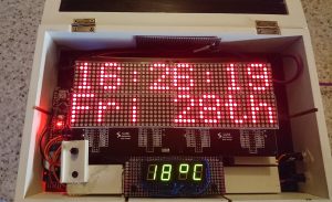
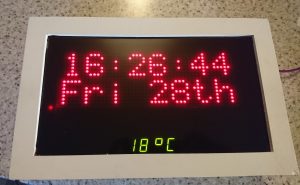
- Bright red LED matrix showing the time in static and animated display modes. 6 modes to choose from which includes a normal time and date, same with scrolling animation, a pong clock mode where the clock plays pong with itself, a word clock and finally a binary clock display mode.
- Optional PIR sensor which turns off the LED matrix when there is no-one in the room.
- Separate seven segment display which shows the time when the matrix is off and temperature when it’s on.
- Displays a custom message at 30 minute intervals on special event days.
- Runs off 5V 1 amp USB phone charger / power supply.
- Uses wooden jewelry box as case although a deep photo frame could also be used.
The code
OK so I made some modifications to Nick’s original design which is version 5.1. My release notes for various versions are documented in the code but I thought I’d repeat them here. This also includes the terms and conditions of the licence and other stuff you should know about if you wanted to modify further and redistribute. I also used Atmel Studio to write the code rather than the arduino IDE but I did check to see if the code compiles with the latest version (1.8.1 at the time of writing) – I did have to make some changes as it came up with some compiler warnings. The last time I did any work was on version 1.6.x and the C++ compiler has been updated since then. The code now compiles in both Atmel studio and Arduino IDE without any warnings or ISO C++ violation errors.
/***********************************************************************
Pong Clock v 5.1, Oct 2013 by Nick Hall. V5.6 modifications by Adrian Smith.
Distributed under the terms of the GPL.For help on how to build the pong clock see my blog:
http://123led.wordpress.com/****Additional notes regarding my modifications****
LM35’s accuracy can depend on supply voltage. When powering from a PC USB port voltage dropped to 4.2V so this method of powering the clock is not recommended.
Don’t place LM35 near parts that will get even mildly warm e.g the shift register chips and the arduino itself. Place away from the PCB preferably outside the case
Use shielded cable if placing sensor some distance away from the Arduino to avoid inaccurate readings and keep analog and digital grounds separate.Current consumption with all matrix LED’s and 7 segment display lit is around 600mA, I used an Amazon basics USB power supply / phone charger with 2A output. Note
that I used a clone nano board, the official Arduino boards have a 500mA polyfuse (some clones may have this too, mine did not) so in this case use a 5V regulated PSU
connected directly to the 5V pin or to the rear of LED panels as the arduino + logic will be powered through the display cable.
Average current consumption is around 400mA but will take nearly 600mA at startup when it tests the display. Matrix boards can get as warm as 36 degrees C.****Release notes for various versions****
Release Notes for V5.6 – code modifications by Adrian Smith
*Replaced jumble with binary clock, jumble not currently able to be selected although relevant function remains in the code. Credits to NeoRame for this.
*Added custom message to display on special event dates e.g birthdays, xmas etc. Again credits to NeoRame for this part of the code.
*Switched clock and latch pins around due to error on my part making the PCB. Doh.
*Added code to convTemp function so it takes temperature sensor readings every ten seconds to smooth out display when on the border between one degree and another
Compiles to 22,984Kb with 1340 bytes of SRAM used.Release Notes for V5.5 – code modifications by Adrian Smith
*Added clock to always on display when main display is turned off by the PIR. Otherwise will display temperature instead.
*Changed decimal point (or colon) so that it flashes once a second when displaying time and once every 30 seconds when displaying temperature (normal mode)
*Used standard AVR C++ code to set pin status instead of using digitalwrite – this improves processing speed by a significant amount.
*Pin 13 LED connected to DP between digits 2 and 3 of seven segment display. If you want to drive a colon instead (2 LED’s) use a transistor to prevent overloading IO pinRelease Notes for V5.4 – code modifications by Adrian Smith
*Added temperature display that is always on displaying on separate 7 segment display. Only uses extra 1% SRAM
*Removed fart detection code as it was just silly 🙂
*Updated so it will compile on the latest IDE (1.8.1 at time of compilation) Char changed to const char for menu texts + millis codeThe 7 segment driver uses high power shift registers with no multiplexing. Yeah I know this is an expensive way of displaying a simple 7 segment
display but with the lack of I/O pins this works well in this project. The code also uses minimal SRAM and flash space so it would fit into an Arduino Nano
eliminating the need for a Mega just for the sake of a few extra I/O pins and more SRAM. Also no multiplexing means no additional delays, minimizes resource usage.
Left hand shift register is the first register (the one feeding the most significant digit)Release Notes for V5.3 – code modifications by Adrian Smith
*Minor changes and experiments with displaying time on a separate always on display but it used too much SRAM
Release Notes for V5.2 – code modifications by Adrian Smith
*Added PIR to turn off display when no-one is in the room so that energy is saved & less attraction to would be burglars whilst you are out.
*Removed play Pong! message
*Pin 13 LED flashes every second to indicate clock is working even when display is off.
*Connected gas sensor to detect farts and displays a message depending on severity of fartRelease Notes for V5.1.
*Fixed a bug in pong mode where the bat missed ball and it wasn’t on the minute
*Fixed a bug in normal and slide mode where the date tens digit wasn’t cleared when some months changed
*Fixed a bug where the display was corrupted in digits mode and also in 12hr mode
*Added lower case font. A tweaked version of the one courtesy of Richard Shipman
*Added full LED test on startup.
*Time is printed to serial port for testing
*Menu and set clock items reordered.Thanks to all who contributed to this including:
SuperTech-IT over at Instructables, Kirby Heintzelman, Alexandre Suter, Richard Shipman.Uses 2x Sure 2416 LED modules, arduino and DS1307 clock chip.
Distributed under the terms of the GPL.Holtek HT1632 LED driver chip code:
As implemented on the Sure Electronics DE-DP016 display board (16*24 dot matrix LED module.)
Nov, 2008 by Bill Westfield (“WestfW”)
Copyrighted and distributed under the terms of the Berkely license (copy freely, but include this notice of original author.)
***********************************************************************/
My changes in particular add a few functions to read the time from the RTC and display it onto the 7 segment display via the shiftout function. There’s also one to read the temperature from an LM35 sensor plus the code to turn off the display if a PIR is connected and no-one is in the room. I found that the shift out function’s digitalwrite calls were slowing down the clock so much so it was quite noticeable when the seconds ticked by so I fixed this issue by using standard AVR C++ code instead of digitalwrite to set the port and pin status. Digitalwrite is a slow function and directly manipulating the ATMEGA328’s ports and pins is a much faster way of doing it. If future versions I may ditch the arduino code altogether so it will run on a standard AVR chip programmed through Atmel studio.
The hardware

I decided to go with Brett’s suggestion as per the overall design of the case and bought the same jewelry box as he suggested as I’ve experimented with photo frames before to house similar projects and I’ve found them to be too shallow or not strong enough / poor quality to be able to house this project. The jewelry box upon receipt is obviously cheap and nasty; it is made of compressed cardboard not wood and the overall quality was poor e.g the lid was wonky, chunks out of one corner and then painted and glue residue on the glass. I tidied it up the best I could and it didn’t look too bad.
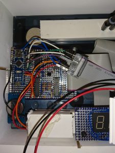
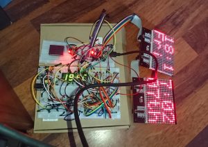
The one thing I did do which was a mistake was to use a prototyping PCB for the construction; I really should have got a PCB made for this despite the extra cost. Also the board I used was a bit on the small side which was a squeeze to get everything on; in fact I couldn’t fit the 16 pin IDC header on the board and used jumper wires from the main PCB to the ribbon cable connected to the LED panels instead. It looks untidy and like a prototype rather than a final product.
I chose to use TPIC6B595 shift registers to drive the 7 segment displays without multiplexing to reduce the amount of arduino pins to only 3 and these 6B595’s can sink a large amount of current to be able to drive LED modules. I used common anode displays as the 6B595’s can only sink current not source it. The modules also needed about 13mA to get a bright display which would be too much for a standard 74HC595. You could use one of these instead but you would have to use a low current, high efficiency LED module(s) that can operate on a few mA of current and still produce a bright display. The ones I used I had in my parts box so I just used them. 🙂

The disadvantage of not using a multiplexed display is increased power consumption (average of 230mA for the LED modules in my case) and a LOT of wires to connect up. As I mentioned above I used a prototype board. That meant lots and lots of mod wire…
The 7 segment displays were mounted onto a small PCB with a 34 pin ribbon cable connecting it to the main board. As you can guess that means about 70 wires to connect from the shift registers to the ribbon cable connector then from the second connector to the LED modules themselves. At this point I thought about scrapping the build and selling the matrix modules on ebay but I persevered. The 7 segment display was really left over from a learning exercise playing with shift registers and I decided to add them into this project. I had a lot of trouble getting the display digits in the correct order as well – note my comments in the code.
Finally I used a DS3231 as the RTC rather than the DS1307 as the DS3231 has a built in temperature compensated crystal which improves timekeeping considerably. I found the DS1307’s to always gain time by as much as 20 seconds a day which is useless for a clock. One such clock I made compensated for the drift in the code which worked but it’s always better to have something that works right in the first place.
Building the things into the case, well that’s up to you how you do it but if you manage to get the same case as me and Brett did then it would be best just reading his well written notes on his website instead of me repeating them here. His website can be found at http://home.btconnect.com/brettoliver1/Pong_Clock/Pong_Clock.htm

I used self adhesive trunking instead of wood to mount the displays to and fitted the whole lot to an insert made of perspex. I also added some metal strips under the insert glued to the base to add some weight so that the unit is not front heavy and likely to fall over. The PCB you can see at the top is yet to be fastened into place and this serves as a power board where I have chosen to use an external 5V router power supply which connects to this board and power then goes to the PIR and to the rear of the LED matrixes onto the aux power input. This is recommended by Sure Electronics. The mainboard and 7 segment display receives its power through the 16 way ribbon cable from the matrixes.
I completed the case by covering the glass with tinted stick on film to improve contrast using two layers of film around the perimeter of the displays to hide the electronics and interior of the case.
Bill of materials
- 2x Sure Electronics DE-DP11112 3mm red LED matrix information board or green version DE-DP11111
- 1x case which is no longer available on ebay but may appear again. A deep photo frame would make a good alternative. Again this would be up to you to find a suitable case.
- 1x DS3231 RTC module. Note that some cheap modules come with a non rechargeable CR2032 battery but are designed for a LIR2032 rechargeable battery. These need modification to the board to avoid the battery exploding. There’s a youtube video explaining this procedure here https://www.youtube.com/watch?v=ND2shVqV9s4
- Arduino nano module
- 4x common anode 7 segment display
- 4x TPIC6B595 or 74HC595 (make sure if you go for the HC595 your LED modules will be bright enough at 3mA)
- 34 pin ribbon cable (wired straight through)
- 2x 34 way IDC socket
- 1x 2n2222 / BC108 transistor
- 1x LM35 temperature sensor
Youtube video of it working
Downloads
Version 5.6 of the pong clock includes Atmel project files, pre-compiled .hex files and eagle schematics.
As above but uses DS3231 RTC and gets temperature readings from the DS3231 internal sensor instead of an LM35. Also stores random mode status in EEPROM.
Noticed bug in word clock mode – replace the font.h in the release download with the fixed version and recompile.
Links and other notes
Original design by Nick https://123led.wordpress.com/about/
Brett Oliver’s page showing detailed construction and some ideas gained from his modifications such as the PIR function. http://home.btconnect.com/brettoliver1/Pong_Clock/Pong_Clock.htm
Instructables page detailing construction https://www.instructables.com/id/Pong-Clock-With-Case/
NeoRame’s version of this clock (binary function used from his mod) https://www.youtube.com/watch?v=4j457sxiPKE
I have credited everyone I can think of in the code and this page, if I have missed anyone please let me know. I will also try and get some better pictures and a youtube video at some point as well. But for now enjoy!


I’ve made a small update today – I’ve also added a version that uses the DS3231’s internal temperature sensor instead of an LM35 to get the ambient temperature. Also this version uses the EEPROM to store the random mode status in the event of a power failure.
The original version is still available for download.
Hi,
I am struggeling to get button a to work. I am using uno and i have made a slight change. i changed it to pin 6 because i want to use an interupt pin when i get round to modifying the design. Should this be an issue? I changed b to 7 and it works.
I assume it is not working as i cant seem to use any menu or am i missing someing?
Thanks
Button buttonA = Button(6,BUTTON_PULLUP_INTERNAL); // Setup button A (using button library)
Button buttonB = Button(7,BUTTON_PULLUP_INTERNAL); // Setup button B (using button library)
Ignore me i forgot to take the code out for the 7 segment display. I am planning to do this with a tm1637
Ah OK, that’s a better solution than mine to be honest. This was really a learning exercise about shift registers and to use up some parts I had laying around. I realised when I started building it I wished I had gone for a simpler solution as there was lots of mod wire connections to make. Also the shift register chips do get quite warm and was affecting the LM35 so I switched to a DS3231 and it’s internal temperature sensor.
The TM1637 should work just fine sharing the i2C bus with the RTC.