The project
I recently bought a few LED displays as a job lot which were parts for fruit machines; the type you see in the local pub and after testing them I found that they had a nice bright red / orange colour to them and decided to use them for a large clock project. As I have not made anything for a while and had some spare time on my hands I thou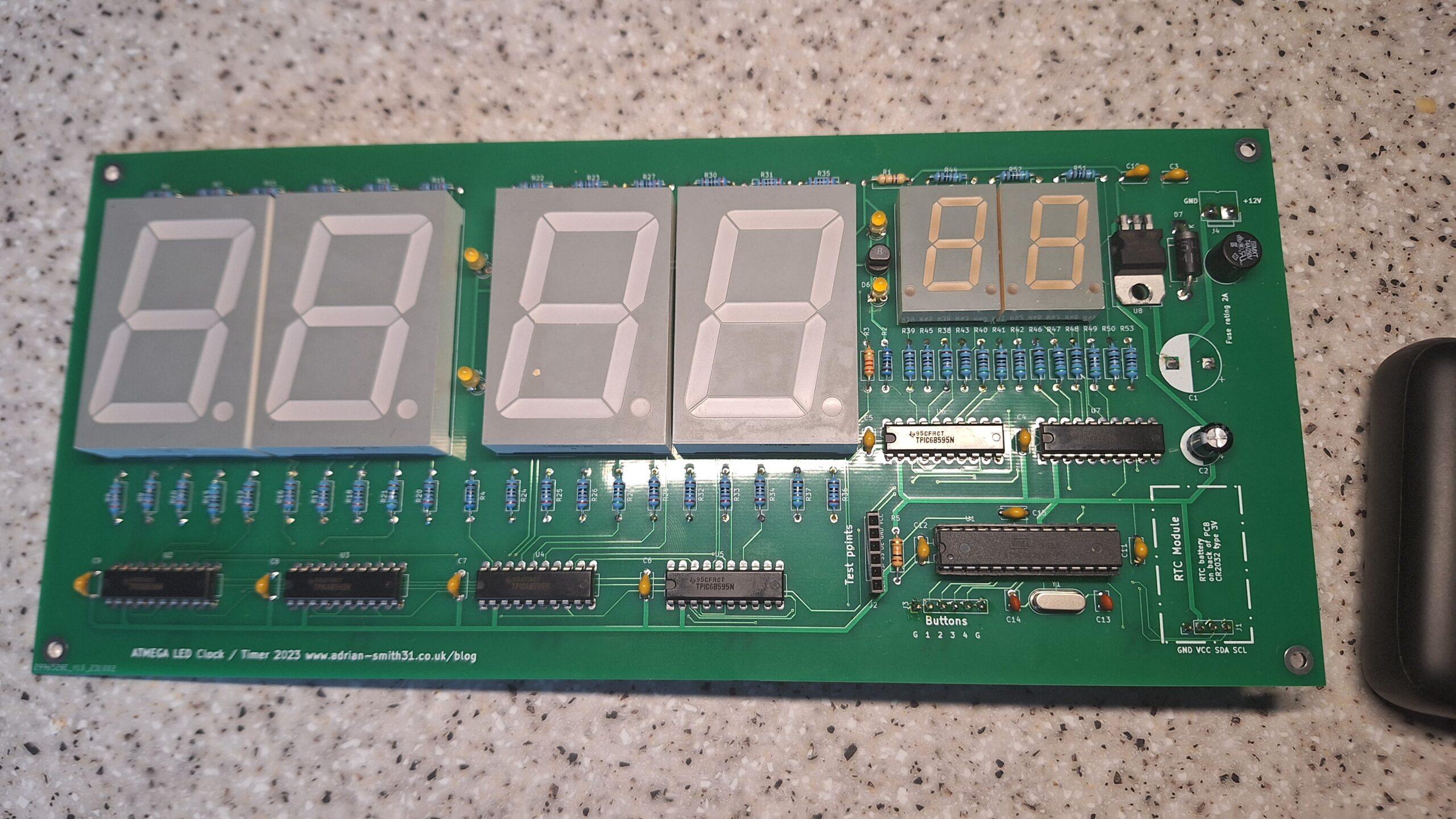 ght I’d need to brush up on my PCB design skills and C++ coding skills. Hence this project – a large LED clock which uses 1.8″ high digits for the hours and minutes and the seconds is displayed on 0.8″ 7 segment displays. It is controlled by an ATMEGA168P microcontroller and uses TPIC6B595 shift registers to drive the common anode displays. A DS3231 high precision RTC completes the electronics. It is a large PCB measuring 270x120mm and can easily be seen from 30 feet away making it suitable for large workplaces or people with limited vision. The clock is powered from a 12V regulated power supply which can supply 800mA or more. A fuse and reverse polarity protection diode helps to prevent incorrect power supply connection from damaging the components. Finally three buttons are used for setting the time. There is provision on the PCB for a 4th button which could be used for something else if I wanted to add extra features later or with the code being open source you could make use of it yourself should you make one.
This project was sponsored by PCBway who kindly offered to make the PCB’s for them. As I have already made the prototypes using boards from JLCPCB I decided to take up their offer and made a slight design change to the PCB layout. I plan to sell these PCB’s along with the remaining version 1 PCB’s on eBay / Tindie so you can make your own if you wish. Please see the links to the right for my eBay store where you can purchase one along with a completed, assembled PCB which I will list in the coming weeks once the button boards and new TPIC6B595 chips come into stock. The version 1 PCB’s are made in green solder mask whereas version 2 has black solder mask. The source code and schematic I will show below and also there is a YouTube video explaining how the circuit and code works.
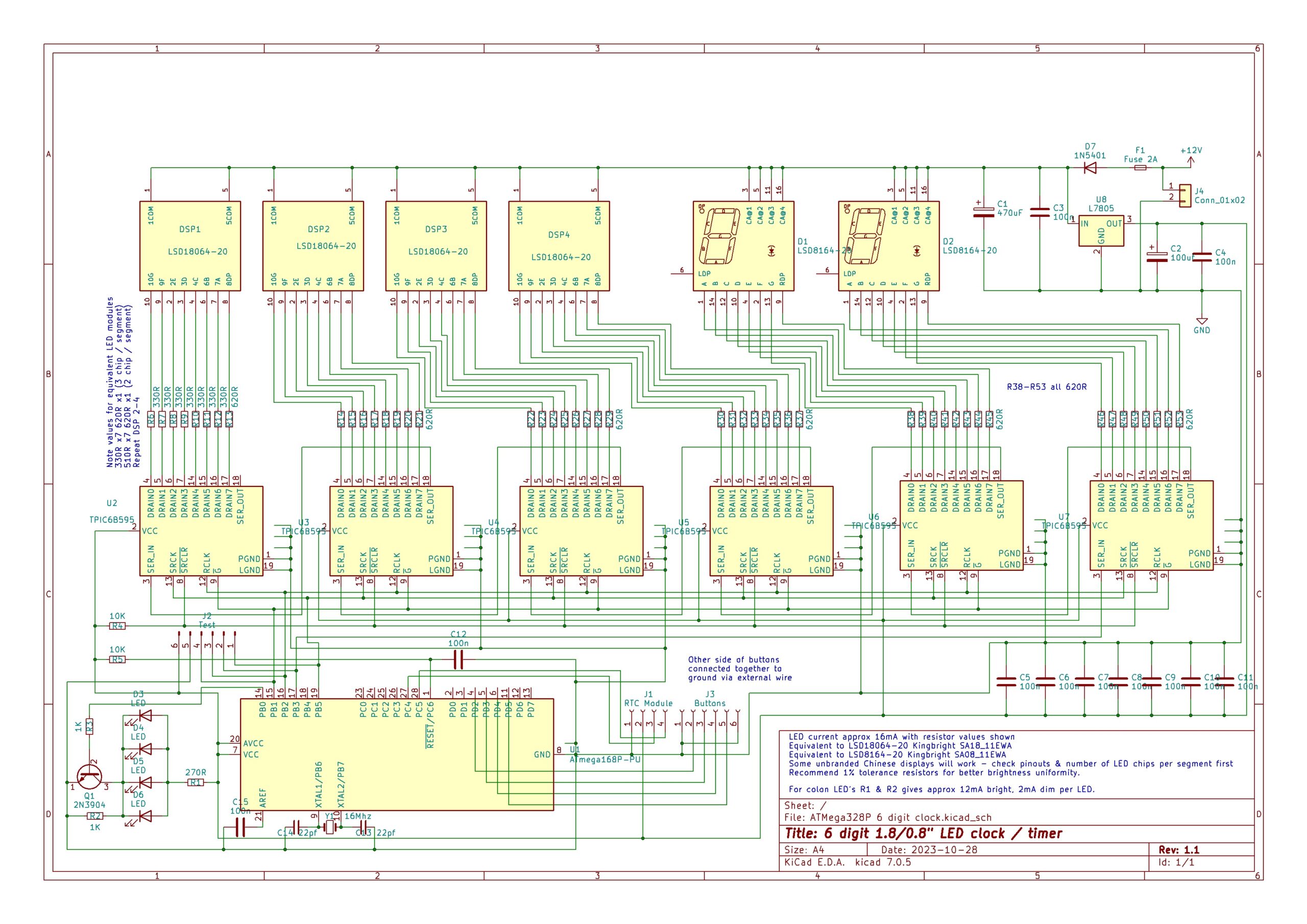
Schematic, code, BOM and YouTube video
Web based simulation of version 2.0 of the clock
Addendum to schematic & BOM – the 330 ohm resistors should, ideally be 390 ohm instead as with some LED displays the seconds display may be dimmer. There’s about 3mA difference in segment current between the main digits and the seconds which is not noticeable on the displays I used as shown on the schematic. But to keep segment current within 1mA use 390 ohm resistors instead. Do not reduce the value of the current limiting resistors on the seconds displays to make them brighter as this would result in too much power dissipation through the resistors. Segment current will be approximately 16.5mA.
Basic use instructions
To set the time on this clock you press the “set mode button” and the clock will show “SEt” for 2 seconds and blank the seconds display. The decimal point will light on the last digit to indicate the clock is in time set mode. Then use the hour button and minute button till the correct time is shown then finally press set mode again to return to normal operation. Note that as soon as you press set time to exit setting mode it will zero the seconds. This way the clock can be synchronised to another time source. For example if the current time is 13:56 set the clock to 13:57, wait till the other time source changes to 13:57 then press set mode button.
Button library compilation issues
If you have problems compiling it could be due to the version of the library available through the Arduino Library manager is different to the one I used which I got from Github. The file versions appear to be the same but some users have been reporting compilation problems. To avoid this download the button library above and place it in your Arduino libraries folder in your documents folder – not the Arduino folder in program files. It should look like my example in the image below.

Closing comments
And don’t forget if you would like to make one of these clocks yourself check my eBay page on the right were I will be listing some of the bare PCB’s and a completed, working PCB when the button board comes in a few weeks. Keep checking my eBay listings for updates. The project is also shared as an open source project on the PCBWay community site where you can order a set of PCB’s directly from PCBWay.com. Finally should you wish to use equivalents of the Kingbright LED displays be aware that the cheap Chinese LED 7 segment displays from AliExpress / eBay / Amazon often do not have datasheets and / or they have non standard pinouts; especially the 0.8″ displays where the pins are on the top & bottom rather than the sides. Also going by what I have found the 1.8″ high Chinese no-name brands have two LED chips per segment rather than three. Whilst this will work just fine you will have to adjust the current limiting resistor values accordingly. Better hope they have that datasheet!
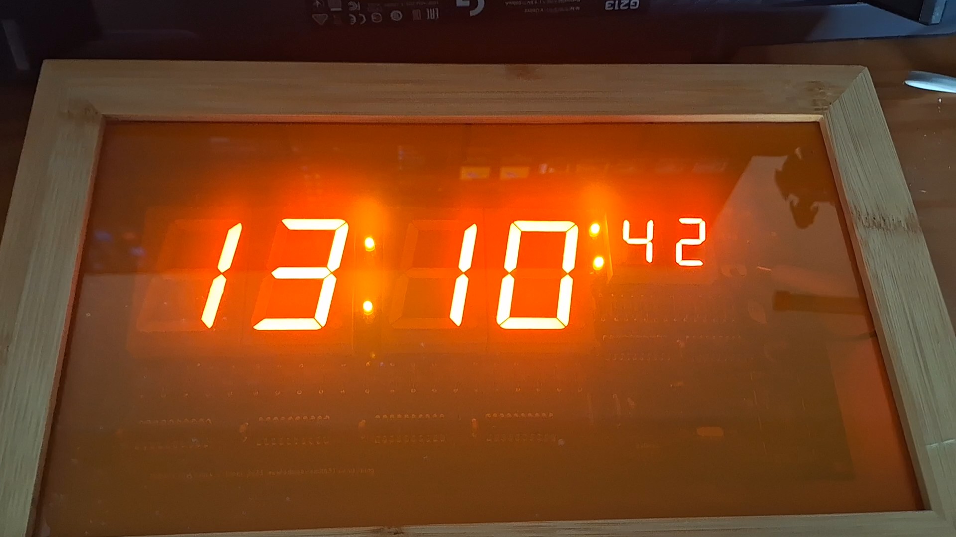
Completed clock in example case.


Hi,
I am experiencing problems in compiling the file for the 6 digit clock to use with a PCB that I ordered from your e-bay add.
“Compilation error: ‘BUTTON_PULLUP_INTERNAL’ was not declared in this scope” appears during the compilation even though I have used the Button library by Alexander Brevig. I have deleted other Arduino libraries that use the Button file to ensure that the smaller Brevig library is called.
Can you help with this query?
Hi David, what version of the Arduino IDE are you using?
I can upload the compiled binary of you need it which can be flashed to the chip with xloader. I’ve replied to your email too. I was having issues with my email spam filter so sorry for the late reply.
Hi, Adrian, Many thanks for your reply. I am using Arduino IDE version 2.2.1. I will try the Xloader route to programming the chip and hopefully this will resolve my problem. Cheers and again many thanks for an interesting project. Regards, David.
Hi Adrian, Your replacement Button library has resolved my problem even though I had used the previous library by the author detailed in your code. Code now compiles error free and has been used to programme a chip with the result that I have a working clock. THANKS again, David E.
Thanks for letting me know. I will put the library I used in with the download on this site as it must be a version issue.
I’ll update the website tomorrow with the firmware code and the library.
Hello,
I have downloaded this library in the past, but for some reason
it gets written over by a different Button library.
Now when I go back to your webpage and click on Button Library
it downloads this different library.
Is it possible to email me or update the link of the original library?
And also, what is happening with the new one is writing over the old one.
I had it working at one point, but was adding some functions , and
keep getting the wrong library.
Thank you for such a good project.
VB
Button library by Alexander Brevig
It could be your Arduino IDE that is automatically updating libraries. The original version used is in the link above in the article which is the same version used in the project. There seems to be compatibility issues with different versions of the button library; the one above definitely compiles. In version 2 of the Arduino IDE if you hover your mouse over the #include “button.h” it will show the file path to the file being used. Not sure why it doesn’t work for some but I’ve not been able to recreate the problem.
You could try putting the button.h and button.cpp in the same folder as the project directory as the code is calling it through #include “button.h” – that way it will force it to call the library from the project folder.
I’ve just tried it and compiles OK.
Check your button library file is dated 27/04/2011. The library is in the list of ones available via manage libraries in the IDE. You want to use the one by Micheal Adams as he seems to have updated it since the original by Alexander Brevig. There appears to be only one version available through the library manager. Make sure it is indocuments>Arduino>libraries too.
Thank you Adrian, for the fast reply.
I will give it a try.
VB
Hi Adrian, we spoke through eBay about the rally timer
Sent you the code via email. Ill remove your email from public view to prevent spammers seeing it
Hi, i am trying to make this clock with smaller 7-Segment displays, and i dont understand how you got the resistor values between the drains of the shift registers and the displays. I am using the DA56-11SURKWA displays. If I could get answer via Email that would be nice.
Hi,
it’s ohms law – it’s anode supply voltage – voltage drop across the LED segment(s) which will give you the voltage that needs to be dropped across the resistor. You need to see what typical forward current the LED displays need then divide the voltage to be dropped by the forward current which gives you the resistor value.
In my example the segments have 3 LED chips with a forward voltage of 1.8V and need 20mA so that is 12V (actually 11.6 because of a diode in the supply voltage but we will use 12V as an example) minus 1.8 x3 = 6.6V to be dropped. 6.6V divided by 0.02 = 330 ohms.
Your LED displays have one LED chip per segment. So you do not need 12V for the anode supply, 5V will suffice. I used 12V as large LED displays have multiple chips per segment and 5V would not be enough to forward bias them.
I would use 5V instead of 12V and use 330ohm resistors to give you a current of just under 10mA or 180ohm to give you a brighter 17mA.
Specs of your display is forward voltage of 1.85V with a current of 10mA (30 absolute maximum)
To work that out it would be 5V – 1.85 = 3.15V now divide 3.15V by 10mA which gives you 315 ohms. Nearest value is 330ohms. This will give you about 9.5mA per segement. You can use 220 ohms for a brighter display which will give you about 14mA.
olá amigo construi o relógio com display de de 4″ obtive um resultado muito satisfatorio, porque ficou muito bonito
pena que não da para mostrar aqui no seu blog. Muito obrigado por partilhar com os seus usuarios.
Hi, thanks, glad you found it useful and you made your own using 4″ displays. Unfortunately there’s no way to upload images here but could you share the images with onedrive / google drive etc and put the link here?
Olá, obrigado, fico feliz que tenha achado útil e que tenha feito o seu próprio usando telas de 4 polegadas. Infelizmente, não há como fazer upload de imagens aqui, mas você poderia compartilhar as imagens com o OneDrive/Google Drive etc. e colocar o link aqui?