Surprisingly even now you can still buy power tools that come with NiCad batteries (not even NiMh) which are a poor choice of battery for power tools due to their memory effect and high self discharge rate. NiMh is a better choice of battery to use but I presume NiMh is cheaper hence why some tools still come with them. I have a bosch drill and hedge trimmer that both use the same type of 14.4V battery which have failed, even the spare one and a cheap Chinese knock off that was bought as a spare. This is simply because they don’t get used often and the batteries self discharge when left in the garage. Upon opening the batteries and checking the cells some of them measured zero volts and were short circuit both in the genuine batteries and the knock off clone battery. Many had leaked too.

The internal cells are around the same size of a C size battery but replacing them with NiMH C cells was out of the question as they would not physically fit into the battery casing. As I had a universal RC charger I opted for lipo batteries and charge them using the balance charger but went without the protection board for the low voltage cutoff. This could potentially be a bad idea but I fitted a small bar graph indicator into the battery pack for monitoring the battery voltage. A push button switch connects the indicator across the battery so it does not drain the battery when in storage.
To convert cordless power tools to lithium the correct way would be to use 18650 cells and a proper BMS board as many others have done. This was my original plan but RC lipo battery packs are better suited to high current discharge rates (many 18650 cells are not, the exception being the ones designed for e-cigarettes) and can handle sudden high current spikes. They can also be charged rapidly too. Using cells from old laptop batteries is not a good idea as some will be in better condition than others leading to cell voltages being out of balance. Also they are not designed for high current discharge rates; larger tools may take 20 amps when the chuck is stalled. It’s always best to use brand new cells and a good BMS board. It’s also worth mentioning that if a BMS board is used you must make sure there is back emf protection inside the drill otherwise this will destroy the BMS board when the motor switches off. If the tool does not have such protection across the motor then a small non polarised capacitor of around 10uf should be fitted across the motor. A high power diode in reverse across the battery (after the switch / trigger) should be fitted too. If this is placed across the motor it would be forward biased when the drill is in reverse. This is assuming the drill simply reverses the motor polarity to change rotation direction. I’ve seen several bad reviews for BMS protection boards purchased on ebay / Amazon saying they failed when used for power tool conversion and the lack of the diode and capacitor is almost certainly why they failed.
Here’s some photos of what I did. It’s nothing too fancy as there’s no BMS board or spot welding to do here:-

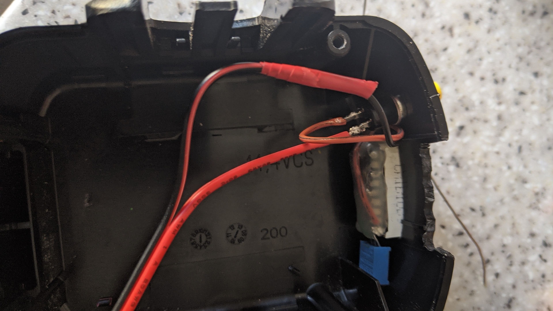
First job is to remove the old cells from the battery casing by removing the four screws and carefully placing the side grips and springs to one side. These can be tricky to remove but bend back to shape if accidentally damaged during removal. This photo is from the Chinese knock off battery but the genuine battery is the same construction inside. There was one thing I noticed on the genuine battery though; they had used a black wire for the positive battery terminal so watch out! This one is colour coded correctly. Verify polarity with a voltmeter after modification.

Once this is done separate the cell inside the vertical tube and the connector block assembly from the rest of the pack making sure not to damage the temperature sensor. The sensor is probably used for the charger for monitoring battery temperature during charging as is the resistor visible on the top of the connector block. This resistor is to “tell” the Bosch charger what voltage to put out to charge the (original) battery cells. The red positive wire from the terminal can be cut off for now but leave a small section for easier removal with the soldering iron later. Cut the metal strip on the bottom of the cell that is connecting it to the rest of the pack. It’s a bit obvious but after conversion to lithium do not use the original Bosch charger to charge the battery! Use a proper charger for charging RC lipo batteries.
Next solder a red cable and black cable to the connector block where the original wires were soldered to. The negative connect to the where the temperature sensor negative is connected to shown in the photo. Use 14AWG silicone wire and cut to a length of around 6 inches so that is long enough to go from the terminals and protrude from the battery casing long enough so that it can be connected to another connector. Solder a male XT60 connector to the bare end of the cable using heatshrink tubing to isolate and protect the solder connections. Next cut a rectangular hole in the lower half of the battery casing so the battery wires can come out without getting snagged. Smooth off any sharp plastic edges. Next it’s a simple matter of placing the battery pack inside the casing and packing with foam so and re-assembling.

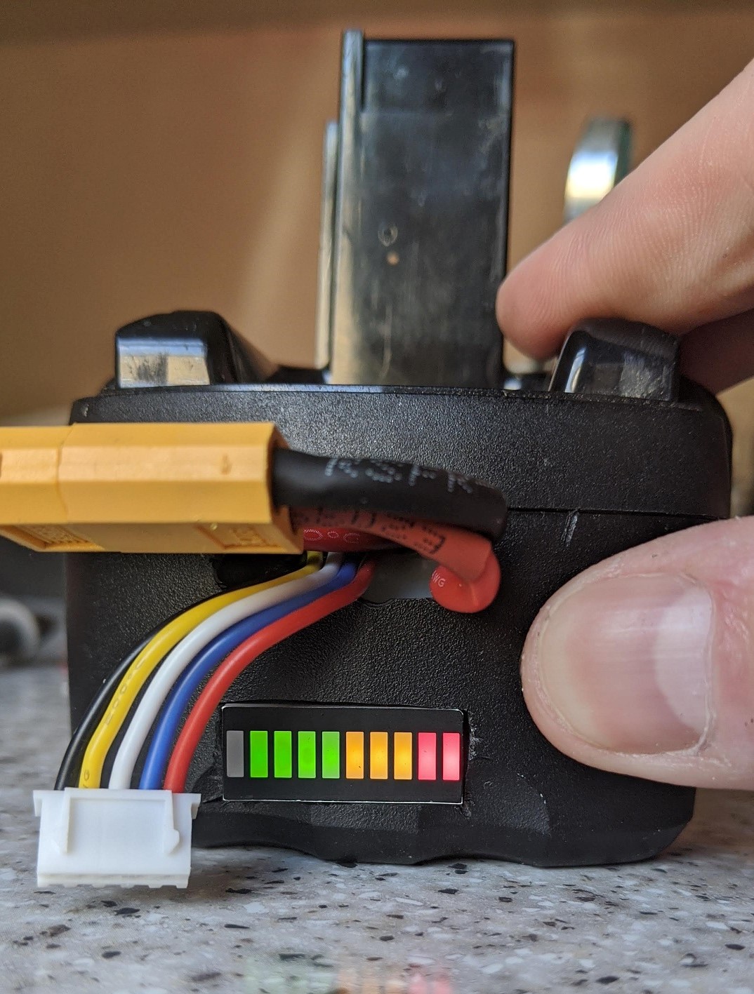
The cables should stick out of the casing like this so that the two XT60 connectors can be joined together and pulled apart and connected to a charger when needed.
I have fitted a voltage monitor to mine which is where the two extra wires come in. I will show photos below of my modification. It basically shows that if the green LED’s are on battery is OK, amber means the battery must be charged and red is that the battery has been discharged to below 3V per cell and should be charged with extreme caution.
The drill this was used in originally was rated at 14.4V and the nominal voltage of the lipo pack is 14.8V (3.7V x4S) however during normal use when the battery is fully charged the battery voltage remained at just over 16 volts even when on load. When it has just come off charge the voltage will be 16.8V which may be a little too high but if I had used a 3S battery instead the voltage would be too low. I hindsight a LiFEPo4 battery would have been a better choice but I was unable to find one that would physically fit into the case. At a nominal voltage of 3.33V this would have produced 13.2V which is maybe slightly too low but may have been sufficient for a small cordless drill. I did notice some excessive sparking from inside the drill when it was shut off so adding a small non polarised capacitor across the motor may fix this. I will try and update later. However an alternative is to gently let go of the trigger rather than suddenly letting go so the motor does not come to a dead stop from high speed.
So here are some more photos for now:-

Long term testing will determine if this is successful or not as I’m a bit concerned that the 16V is just a little too much voltage; maybe an alternative is to charge the battery to 80% which will increase it’s lifespan but not it’s runtime. I only used a 1.6Ah battery for this project which was chosen with the limited space inside the original battery casing in mind. If the worst comes to the worst and my drill burns out it’s no great loss as it would have been scrapped anyway as it wouldn’t have been worth buying another expensive battery pack for it to only sit in the garage and deteriorate.
Hope this is of use to someone.

