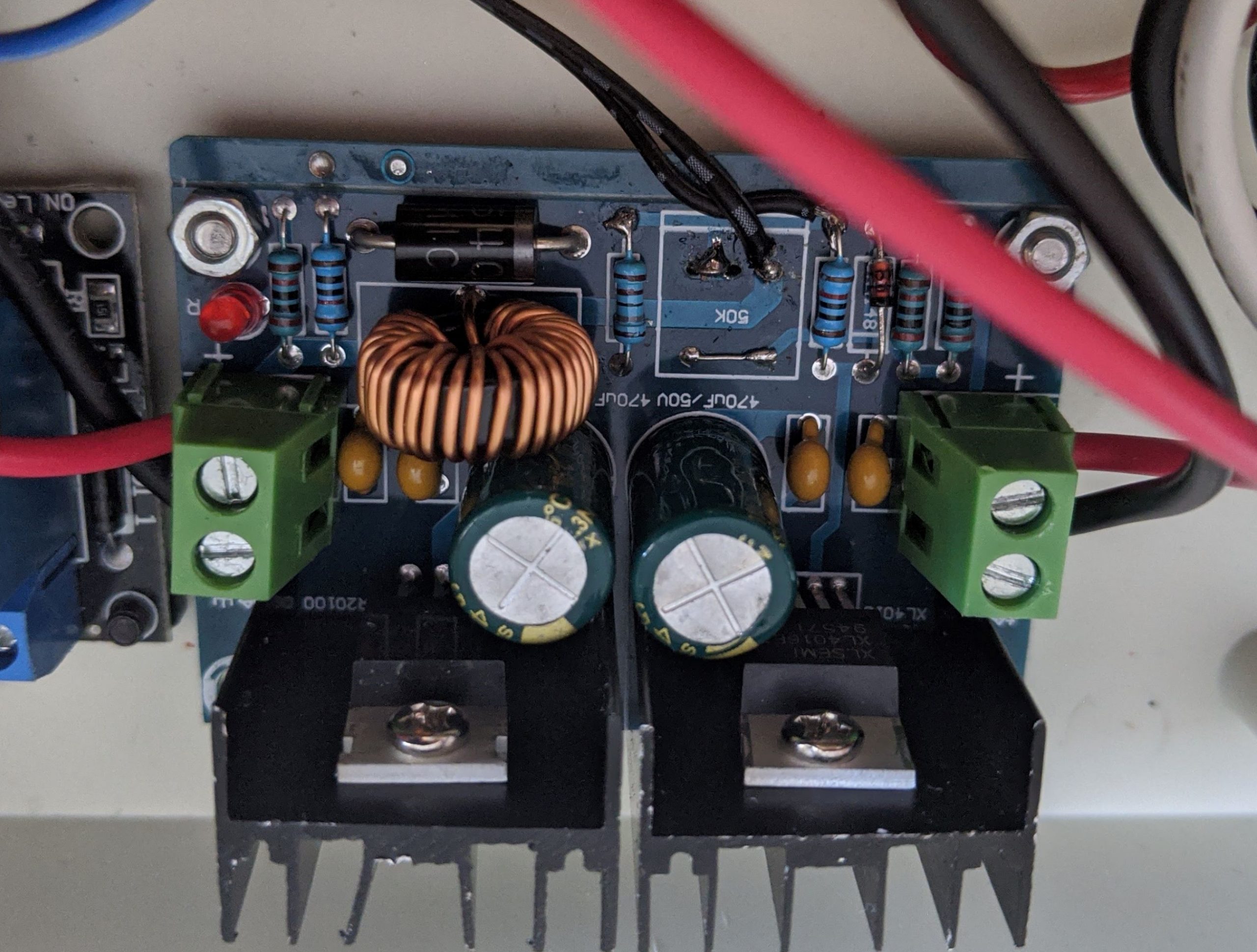
I am building a basic power supply for a project and decided to try one of the XL4016E1 based regulator modules commonly available on eBay, Amazon and Bangood which is advertised as being able to handle an 8A / 200W load. I only need up to 2A for my project but at £7.99 it seemed like a bargain and much cheaper than building my own regulator. The one I bought looks like this:-

I bench tested the unit with an input voltage of 30V (the board can handle up to 40V) and subjected it to various loads most of which it handled well. The major issue with this regulator is that it is almost impossible to set the output voltage accurately as the potentiometer is only single turn and the slightest touch makes the voltage jump around. It is very sensitive particularly at the bottom end of the scale e.g if you are wanting to set it to 5.00V then this is almost impossible but say 26.55V then this is easier although it is still difficult. I replaced the potentiometer / switch assembly with a 50K multi turn pot and bridged out the switch pins. The photo below shows the modification I made. The fitted potentiometer was difficult to remove and I inadvertently pulled out some of the board’s through hole plating and tore a PCB trace. I managed to fix this and the board works fine. However even with a 10 turn pot trying to set an exact output voltage to within 10mV was still difficult at the bottom end of the scale.
Otherwise this seems like a good little module. It can indeed provide a decent amount of current (I only tested up to 5A) and it maintains regulation well at low currents. However at currents above 3A the regulation starts to diminish and at a current of 5A there was almost 400mV drop on the output voltage when the load was switched on. The heatsinks do get rather toasty at this current so the manufacturer’s recommendation of using a fan at currents above 5A is definitely needed. They were way too hot to touch after 10 mins of running. The red LED on the board only comes on when the output voltage is around 2.5V and it’s brightness depends on the output voltage. Some of the the 180Khz switching frequency noise is on the output however so this may need additional filtering if this is being used to power anything with analog circuitry. I don’t have an oscilloscope to hand but the noise was significant enough to show on my multimeter’s built in frequency counter. Build quality wise, it seems OK with a good quality PCB and components soldered neatly and no flux residue etc.
Other problems and snags are the mounting holes are too near the heatsink making mounting it to a case harder than it needs to be. You can’t fix with a M3 nut and bolt for example without catching the heatsink. The input and output connections are not labelled in English either; all text on the board is in Chinese. No instructions were provided but the input is on the left and output on the right looking at the board with the pot facing you. On the subject of the pot, the supplied knob is really crappy and split as soon as it was pushed onto the pot shaft.
So is it worth purchasing? Yeah it is if you don’t need precision output voltages or a lot of current. Otherwise you need to pass on this one and find something of better quality. If you were say using it to power 5V critical projects such as microcontrollers you will definitely want to swap out that pot with a 10 turn or better multi turn pot. You only need 2 wires – one to the wiper and one to one of the other ends. You will also need to derate the advertised current capability by half so in reality it is up to 36V at 4A. In my application it’s going to be used in a bench PSU so the board gets it’s power via a transformer and full wave rectifier. I’ll be showing this when it’s done as I’ve added some features such as an electronic fuse and soft off / on. The output current will be limited to 2A and it will have a range of 1.2-20V. Long term reliability can then be determined and I will update here but for now it seems to be worth the money despite it’s flaws.


Dear Admin,
Thank you for sharing the information about your project. I’m about to start my low level signal project and planning to use linear regulator. I was reading this article https://www.derf.com/an-overview-on-voltage-regulators/ and as my per understanding it would be good option.
As you have used voltage regulator for you project. Could you please give me any useful advise especially do’s and don’ts.
I’d appreciate your help!
Jason
That depends on what your project’s power requirements are. As you have said it’s a low level signal I’d guess it does not need much. If you only need a single voltage then a fixed regulator should be sufficient as long as the voltage you need is available in a fixed regulator.
The 78x series regulators are good. One thing to be aware of is switching noise from switch mode regulators can affect analog circuits and it’s best to use linear regulators if possible.
This one in this post is a switching regulator.