I built a bench power supply for a relative which had to be low cost and I decided to use Bangood as my source of most of the parts to reduce cost. I purchased the case, relay module, DC-DC converter board, panel meter and the output banana jacks from Bangood and the rest came from my spares box. I had a number of issues with these cheap parts as they didn’t work as intended or simply just didn’t work. But more on that later.
The XL4016 based switch mode DC-DC converter board only allowed you to adjust the voltage output and it did not have a current limiter on it. The module is rated at 8 amps output but the tiny heatsinks suggest that it’s probably half that and the transformer feeding it is only rated at 2 amps max. I did a review of the XL4016E1 DC-DC converter module separately; see this link for the first impressions and the flaws I found with it.

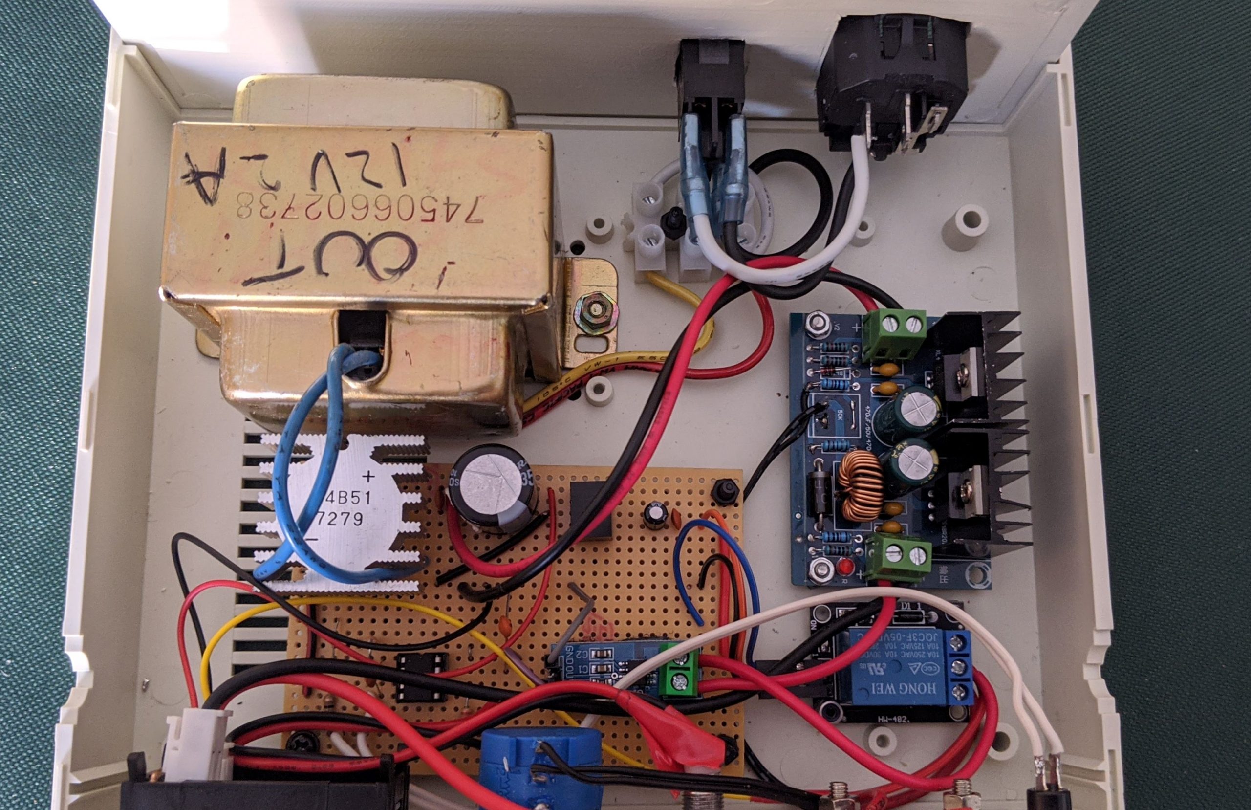
So I decided to make an auto cutout circuit that works by monitoring the current via an ACS712-5A sensor. The ATtiny85 switches the PSU load on and off via a push button toggle. Useful as the module I’ve used does not have remote off / on facility and it’s handy to turn the output off whilst connecting up your projects rather than having it permanently on. When the output is on the sensor is read and if the current goes above 1.75 amps the output is disconnected and a red LED lights. A green LED indicates that the output is on and all is OK. I used a dual colour LED that simply turns red or green depending on condition. Originally I was going to measure temperature of the XL4016 module too using an LM35 but there were not enough pins on the ATtiny85 and the switching noise from the module produced erratic analog readings that I could not fully filter out. This didn’t present a problem with current sensing however.
The rest of the power supply was built on veroboard which contains the rectifier bridge and the voltage regulator for the ATtiny85, current sensor and relay module. The transformer was salvaged from some old audio equipment and testing revealed it could handle 1.6A continuous with 2A peak. This was determined by voltage drop and if any excessive hum was emitted and looking at the fuse ratings on the equipment it came from.
The power supply works well although I had a few problems with the cheap parts and had to change my design or modify / adjust the components. First of all the DC-DC converter output voltage adjustment was way too sensitive and needed to be replaced with a multi turn pot. The panel meter a DSN-VC288 was just practically useless with the voltage and current readings way out. There were a couple of trim pots on the rear that required adjustment to get the voltage reading reasonably accurate as adjusting it made it OK at low voltages and way out at higher voltages so somewhere in between had to be used. It’s only accurate to 1 decimal place but it was half a volt out at 5V. As for the current, this was even worse as even after adjusting the trim pot to the minimum setting it was still about 30mA out. This is something I’m going to have to look into further or just subtract about 30mA from the actual reading displayed.
The other issue is this PSU was originally going to supply up to 30V at up to 4A but the tiny heatsinks on the XL4016 are woefully inadequate getting scolding hot in under a minute so I had to derate to 20V / 2A. Even a fan would not have helped; the 8A rating is a joke really as the thing would practically burn itself out if subjected to that kind of load. The final problem was the case had a foot missing and the screws go through the feet to hold it together so I had to make my own. Oh yeah the output binding posts are just shite; one turn of the wire clamp results in it falling off. Upon inspection the thread has been pre-stripped from the factory. Just for me; thanks bangood!
Now enough of the hardware and on to the software:-
The firmware uses David Mellis’s board support at https://github.com/damellis/attiny which will need to be added to your Arduino IDE to be able to program the bare chip. This can be done by adding the link provided in the firmware download to your arduino’s preferences>additional board URL’s. The ATtiny85 and others in the supported ATtiny family will show up in your boards list once updated.
Programming the ATtiny85 from the arduino software is easy. You will need an Arduino board such as the Uno programmed with the Arduino as ISP sketch (in the examples) and then connect it to the ICSP pins on the ATtiny85 and obviously ground and 5V. A 10uf capacitor needs to be placed between reset and ground on the Arduino to prevent it resetting when used as a programmer. You will need to then choose the correct chip in the boards manager and select 16Mhz internal clock option. Then change programmer to arduino as ISP in the arduino IDE. Then go to burn bootloader. This does not actually burn a bootloader but simply sets the fuse bits on the ATtiny85 chip. Once that is complete you can then upload the sketch as you would normally.
Don’t forget to change programmer type back to AVR-ISPMK2 in the arduino options once you are done. If all is programmed OK, the green LED and the switching relay will turn on and latch on. Press again to turn off. If the output is overloaded above the set value in the code or shorted out the relay will turn off and the LED will light red. Press the on button twice to reset and turn on the output again.
I did try and develop this on a digispark development board but it was a waste of time. The components on the board such as the USB pullup resistors and LED interfered with the operation of the program especially the analog inputs. I had to use an external pullup resistor on the button pin. These little boards are OK for very simple things but if you want to use any pin that’s also used for the USB connection it does not always work. There’s a 1.5K pullup resistor on the USB+ pin for start.
So to sum up… is it worth building your own bench PSU from cheap Bangood / eBay / Amazon parts? Well that depends on if you are doing it for the experience or want something reliable or not. In my case this was for a relative who didn’t need high currents or high voltages. But for most of us no, I wouldn’t recommend building your own DIY PSU. You can buy one fairly cheap however some of the cheaper ones may be just as crap as the pre-built modules. You need to be spending at least £100 / $100 on a “decent” single output PSU if you are wanting something cheap. I use a Tenma PSU which is Chinese but is an excellent quality unit. That cost me about £150. Alternative would be to purchase a second hand quality brand from eBay.
One gotcha you have to watch out for is switch mode power supplies produce digital noise and this can be problematic with analog circuitry. I personally prefer linear power supplies which are heavier but work better for hobby use when I’m working with microcontrollers and analog to digital converters.
So that’s it really. Next possible project is to build a PSU based on the modules with a colour screen and full digital controls to see how they perform. A quick total up of parts cost is comparable to buying a branded complete PSU so this is something I may attempt depending on how bored I get at home.
Please note that the schematic shown below is based on a design that uses a transformer with two windings which provide 36V and 9V approx after being rectified. The final version used a single winding transformer rated at 16V AC (21V approx DC) at 2A and the front panel meter was powered from the unregulated 21V supply.
Download the ATtiny85 electronic fuse code here
Youtube video

