I have been trying to see if the Merlin Helicopter CDU I wrote about in my previous article could be repurposed. I found that it has a number of serial ports which are a mix of RS485 and RS232 and was hoping that key presses would present something on the serial port(s) or the display could be controlled via the ports. The pinout of the large 26 pin connector can be found here.
I found that one serial port is connected to the processor board and outputs diagnostic information once booted. This is a strange one as all ports are 57600 baud, no parity and 2 stop bits. The ports all output 0123456789 briefly a second or two after power on and during loopback test but the port connected to the processor board switches to 19200 baud, no parity and 2 stop bits then dumps some diagnostic information shown in the image below.
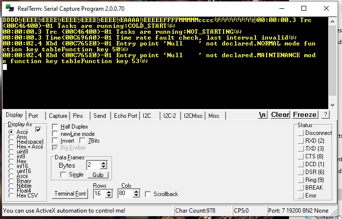
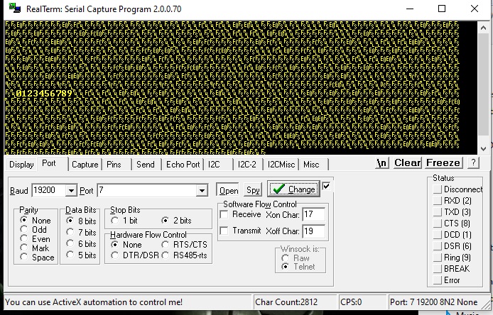
I wasn’t able to get anything else by pressing the keys nor able to get it into maintenance mode either by pressing “S” (53 hex) nor via the serial menu. I tried sending various commands but it would not move off the CCS Failure message on the screen. The error message entry point not declared seems to imply that the RTOS cannot find a particular task (application) to execute. Have it been purposely removed or is it just because it isn’t connected to the rest of the aircraft’s systems? I tried the other RS232 port but that outputs nothing at all nor responds to commands. That leaves just the RS485 port and the TTL level serial output which also just sends 0123456789 at boot and loopback test. Nothing is output when keys are pressed and the unit does not respond. The garbage shown is 0123456789 if switched to 57600 baud as in this image:-
It seems odd that it defaults to one baud rate then switches to another for the diagnostic menu. However I’m saying menu with a pinch of salt as it does not show any choices nor respond. I’m guessing it’s just a diagnostic output. From the messages it’s displaying I’m saying it’s normal as it can’t communicate with external systems and is unable to run the programs. I guess this runs some kind of RTOS such as VXworks although there is no licence on any of the PCB’s so it may be a custom OS. Getting the firmware image off the board(s) is difficult as they are surface mount flash chips rather than socketed ROMs in older equipment that could be plugged into an eprom reader.
The RS485 output simply looks like this in the image on the below right:-

As you can see it’s just the loopback test. This requires all four wires connecting as it operates in full duplex mode. However as with the other serial ports nothing is output when keys are pressed and during any of the other tests. Sending various things to it has no effect.
For the time being I’m having to put this aside as I don’t think I’ll be able to do much else with it. I could find out what the 14V voltages are connected to as they don’t appear to be signal lines or for power. I’m guessing they are function enable pins by pulling the relevant pin low but I couldn’t trace where they went on the PCB’s. Maybe something for some other time. These are connected to transistors which in turn are connected to the MIL-STD-1553B transceiver module.
I’m guessing that the reason why this won’t do anything is because it is likely a slave device on the 1553B bus and is waiting for a command from the main computer before it will send anything back. In a hardened military application it does not seem logical a standard RS485 or RS232 interface will be used to send or receive sensitive data. These ports were likely used for auxiliary systems or sensors and the CDU communicated with the communications system and / or main computer over the 1553B bus.
For now it will go into the things to play around with when I’m really bored or may strip it for parts. I thought about replacing that plasma display with an LCD as it isn’t controllable with an Arduino but there isn’t really any point as I don’t have a use for it yet.
If by the extremely slim chance that anyone does have any technical information on these units I would be grateful if that could be shared.
Update on this: the other TTL level RS232 port I traced to an RS232 level side of one of the transceiver chips and hence could be connected to a standard serial port so it’s not TTL level like I originally thought. Signal is 5V P-P though. This port was likely used for the CCD which stands for Cursor Control Device (a mouse / trackpad / trackball) rather than Charge Coupled Device. Especially with it being connected to the processor board like the diagnostics port. That leaves the RS232 port that does not do anything and the RS485 port which presumably is for the AKU which I still don’t know what that stands for.
As for the display module briefly mentioned above it is not a plasma display panel it is a TFEL panel manufactured by Planar and has the same pinout as the commercially available module part number EL320.256-F6. Nice.

