With lockdown continuing I bought some more military surplus aircraft avionics to mess around with to pass the time and try and figure out how they work of if they could be modified for some other purpose. This time I have a RAF Merlin helicopter CDU (Control Display Unit) to strip down and see if I could power it up. This is the most modern piece of hardware I have got so far dating to 1998 with a sticker suggesting it was repaired in 2002 and it consists of modern surface mount components. It is manufactured by Racal Avionics (now Thales Avionics) in the UK! which is not something you see often nowadays. Actual British electronics and not made in China!

The unit was marked as unserviceable due to broken fixing bolts so it would not stay secured however it is fully functional otherwise. Furthermore the RAF transferred all of their Merlin helicopters to the Navy where they were upgraded and hence these units are now obsolete and were picked up from a military surplus seller. There wasn’t any information on this unit and searching Google brings up no information either other than photos of the Merlin cockpit with the pilot interacting with one of these units; there are two per aircraft. Prince William may have even flown one of these models of helicopter and could have even used this particular unit however I couldn’t find anything suggesting that.
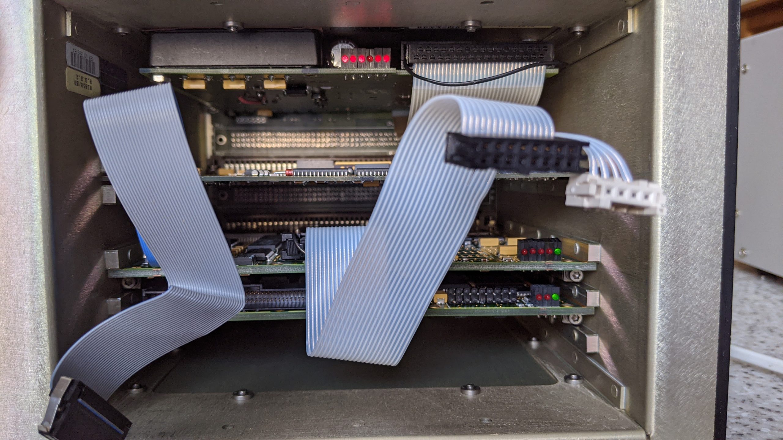
The unit consists of three circuit boards and a keyboard / display front panel which uses a orange plasma display panel (like the very first laptops) but the display is inverse i.e amber on black rather than black text on an orange / amber background. Update: the unit actually uses a TFEL display (Thin Film Electroluminescent Display) made by Planar and it has the same pinout as the commercially available part no EL320.256-F6 and there is a datasheet available. The circuit boards are the interface board containing an 8 bit microcontroller built into the MIL-STD-1553B interface module along with several RS232 / RS485 transceivers, UART chips and custom CPLD chips amongst others.

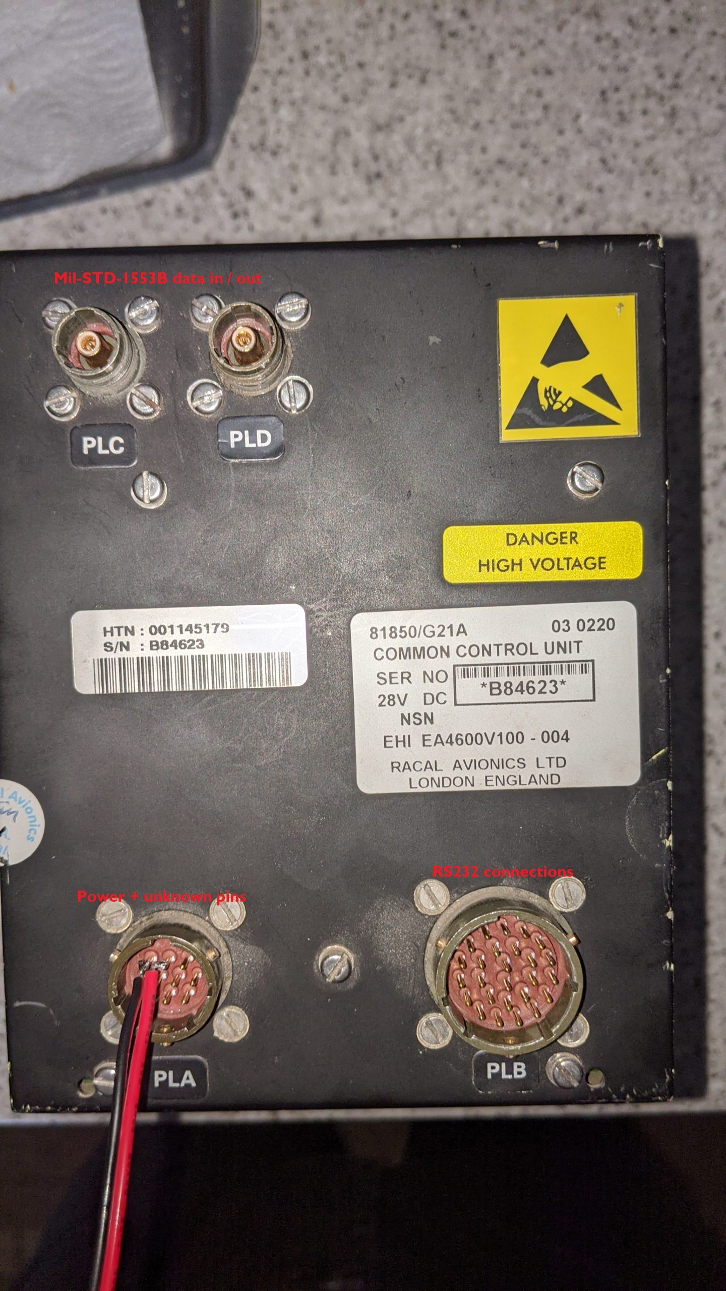
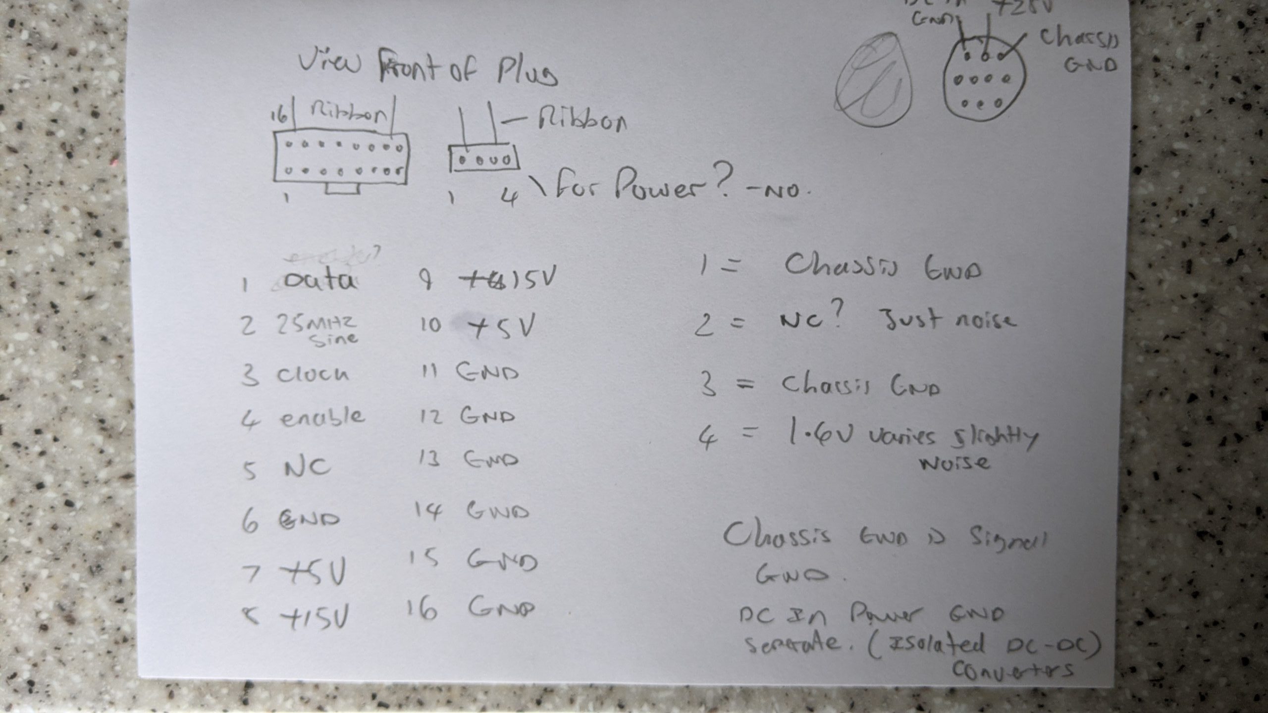
The second circuit board serves as a display and keyboard interface and contains an AMD 32 bit microcontroller and some fast SRAM and various support IC’s. This board, unlike the others does not appear to be connected to the rear panel connectors; instead simply serving as the keyboard and display controller. Speaking of the back panel there are two circular aircraft style connectors; the smallest is for main power and lighting along with some other unidentified inputs; possibly external switches to select function etc. There are also two coax MIL-STD-1553B connectors and a large circular connector that carries the serial input and outputs.

The third and final board is the main CPU board powered by a Motorola 68EC020 @ 25Mhz supported by some SRAM, 1Mb of flash and various 68×000 support IC’s and more UARTS. There are also more RS232 / RS485 transceiver chips two of which connect through to the largest plug on the back of the unit. Almost all of the IC’s used on the circuit boards are still in production and have datasheets available which makes modifying it a little easier although it does make heavy use of CPLD chips for specific functions.
The unit does not do anything on it’s own other than display “CCS failure” which is the Communications Control System so as you can guess this CDU is for communications further evidence is on the screen; it has severe screen burn and image retention showing ghosts of the former menu system. It does have a test function where the keyboard, serial interfaces and links to other systems can be tested and options for turning auto brightness on and off etc. Of course most of these tests fail due to not being connected. It connects to an AKU (not sure what that is) a CCD (presumably Charge Coupled Device) edit: confirmed to be Cursor Control Device (a trackball mouse basically) and the main aircraft computer along with the CCS. I presume these CDU’s are all the same, just firmware and keyboard layout allows it them to be used for other functions such as navigation. I’ve seen photos with three of these in the cockpit each controlling a different system. Unfortunately they are all too low resolution to be able to see what is displayed on the screens or show the cockpit unpowered.

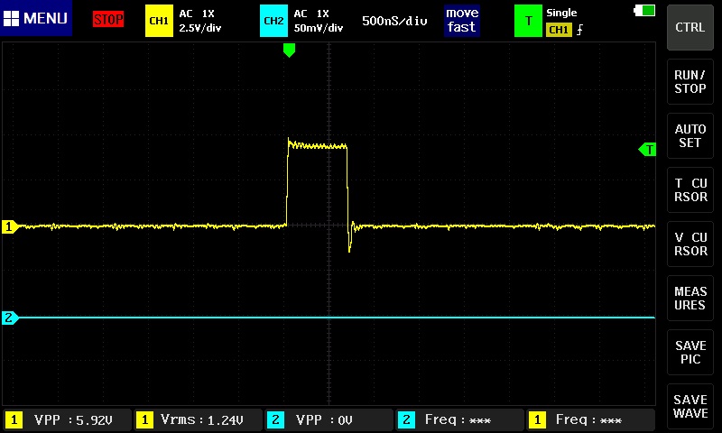
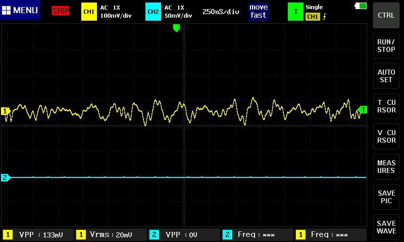
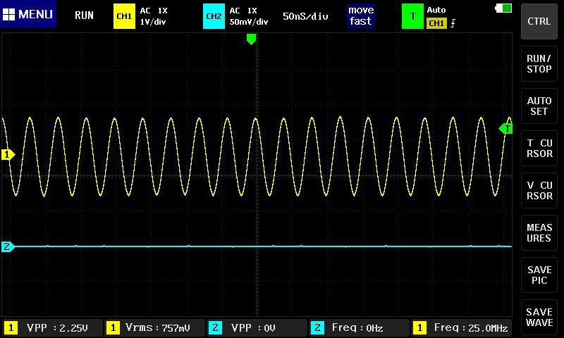
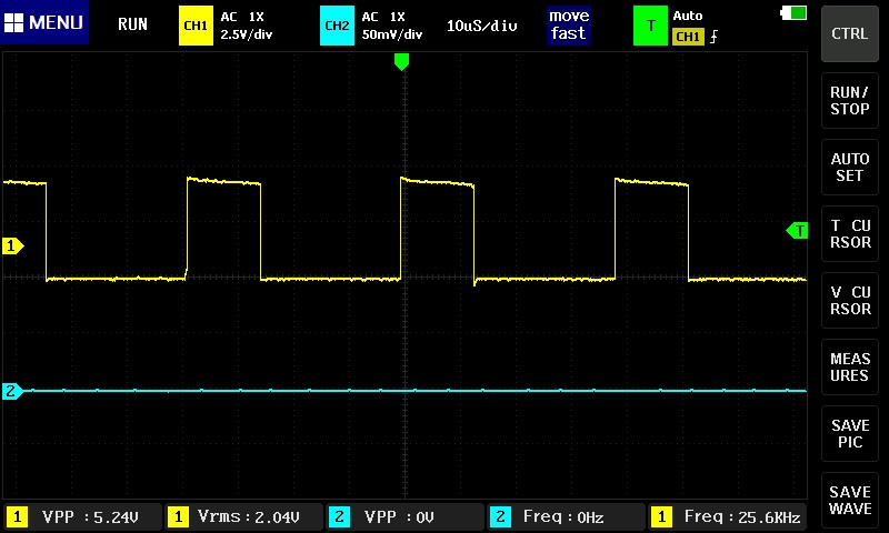
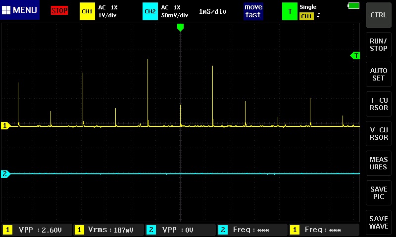
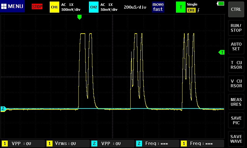
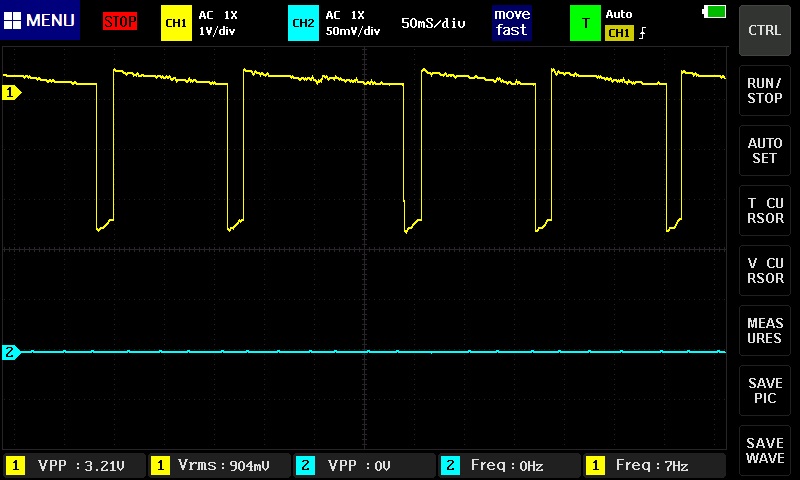
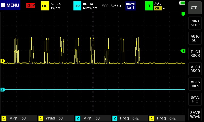
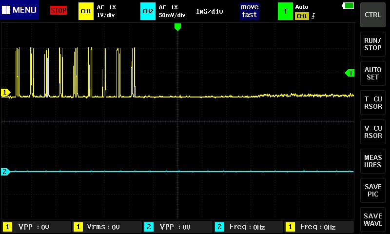
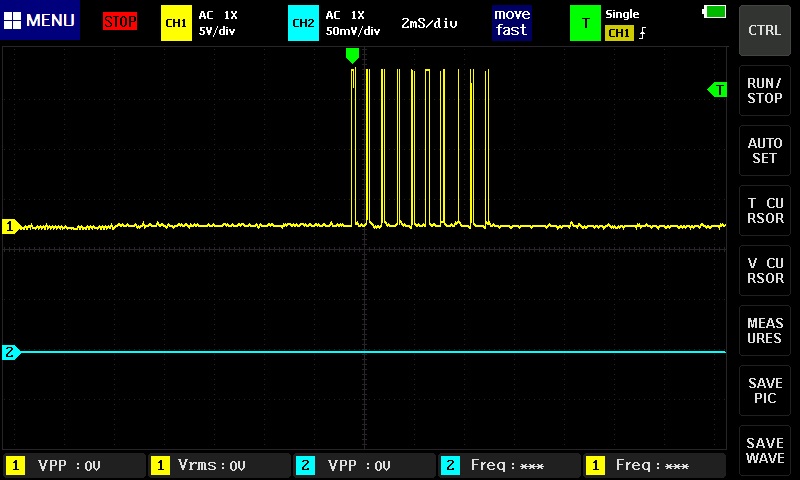
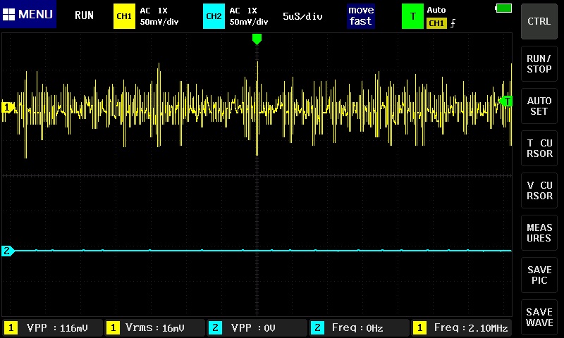
If I could figure out those serial commands I could possibly do something with an Arduino to make it do something or use it’s keyboard to control something assuming the serial data from key presses are present on the rear plug. Another possibility is remove the TFEL panel and replace it with an LCD powered from an arduino mega and removing the internal circuit boards. The display panel is too worn out to be any use and requires complex drive circuitry which really needs an FPGA or fast CPU to drive at a usable refresh rate; an 8 bit Arduino just won’t cut it. The CDU however could serve as a cool control panel, for what I have no idea yet maybe for gaming. I don’t play flight simulators but it would be ideal for that if it could be interfaced to a PC via an arduino or raspberry pi. I did get some waveform captures with an oscilloscope on the display data connector and on the rear plug when a self test was running. There was only one signal present on the rear plug when sat displaying CCS failure.

Not sure what to do with it yet but it will go on my things to play around with when I’m bored pile along with some of the other things I’ve bought. Or I may resell it on eBay although the seller I bought it from has loads of these so I don’t think it will sell. Maybe it will be worth more in a few years time especially if it works. All it needs is 28V at 600mA to work.
If I manage to do something useful with it I will post another article.
I made a YouTube video showing the disassembly and operation of the unit along with the captured waveforms and images below.
Here are some more photos of the unit along with waveforms captured on an oscilloscope which shows that the serial data format appears to be 8 bit with a parity bit and one stop bit although that will need to be confirmed later once I get a USB to serial adaptor. Edit: I have now confirmed that the serial ports operate on either 57600 baud or 19200 baud with 8 bits and two stop bits. Please see my latest article on capturing the serial outputs and (unsuccessfully) trying to get it to work.


One thought on “Merlin helicopter CDU teardown and power up demo. Three microprocessors inside!”
Comments are closed.