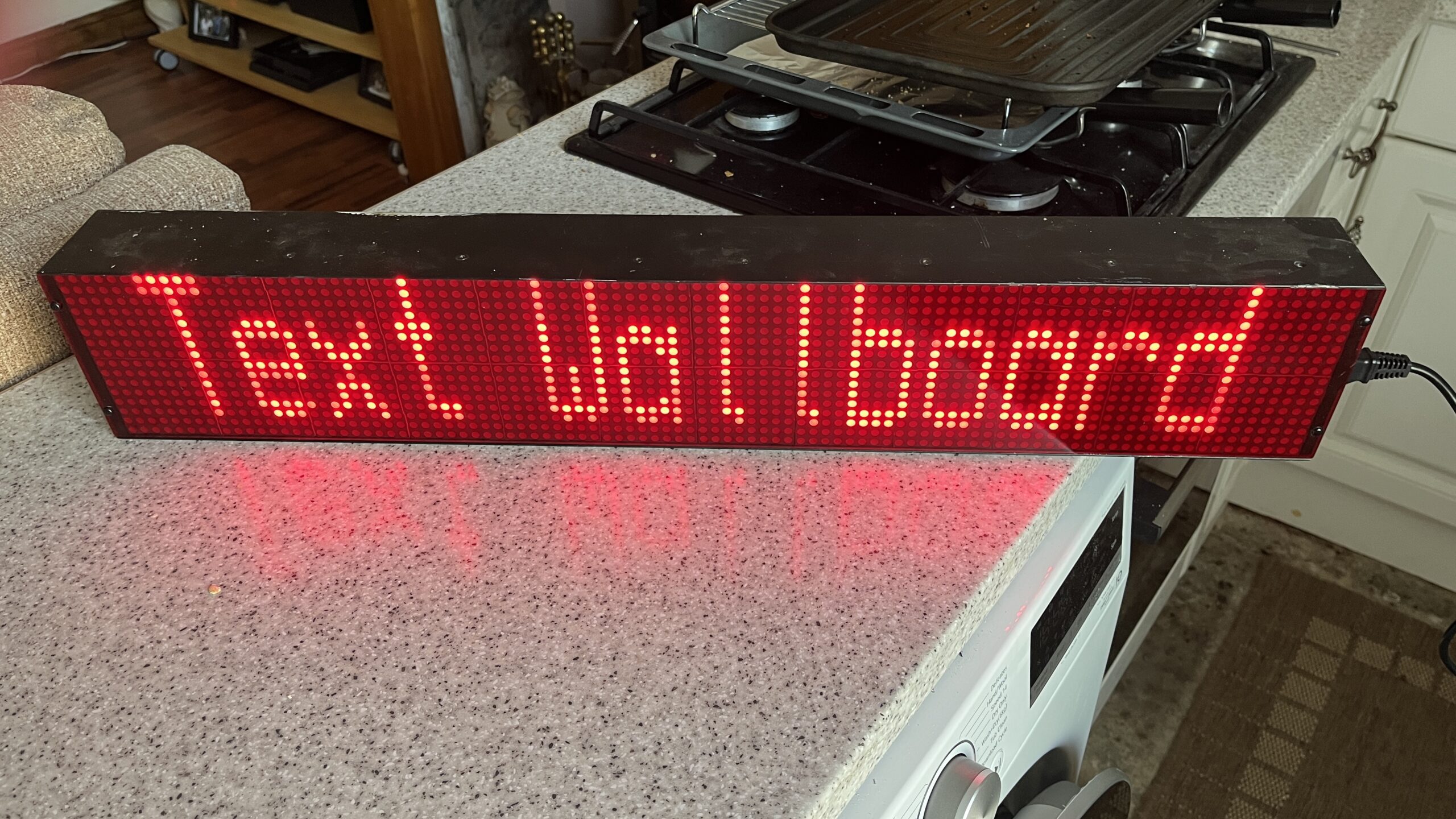
I recently acquired a few scrap Seltek (now Avaya) wallboards from an insurance company’s call centre, and they turned out to be quite intriguing. Among the items were three call waiting monitors and a SDX ACD scrolling message display, also known as a “wallboard.” What caught my attention were the separate LED modules in the scrolling message display, which seemed salvageable for either electronics projects or selling on eBay.
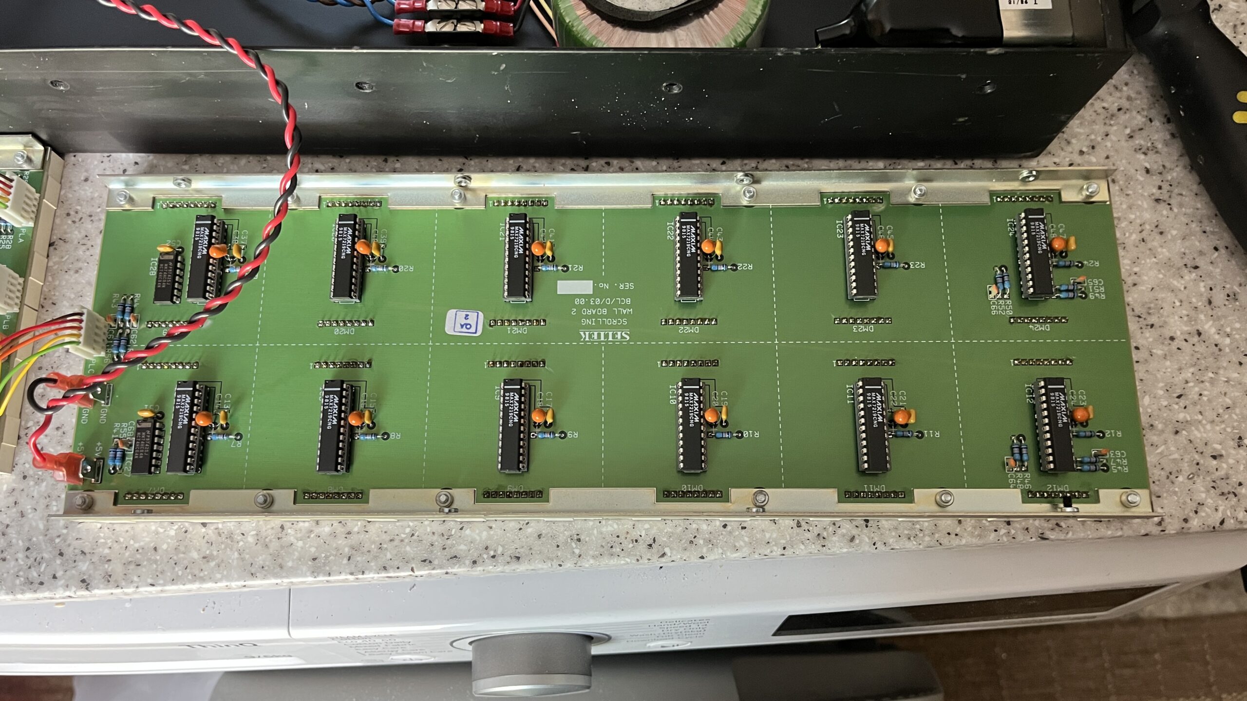
Inside the display, I found two matrix modules, each comprised of two lines with six 8mm square LED matrices featuring 5mm LEDs. These modules were controlled by a MAX7219 driver, and the entire system was controlled by a logic board utilizing an Intel 80C186 CPU. Additionally, there was a nice 5V power supply module and a toroidal transformer.
Unfortunately, I couldn’t establish a connection between the wallboard and my computer in its original state. Despite my attempts to uncover the serial protocol with some assistance from the YouTube user killergeek, I didn’t make any progress. I suspected that my USB to RS485 adapter might not be functioning correctly, or perhaps I wasn’t using the right baud rate. Nonetheless, the wallboard presented valuable components for future projects, and I’m considering using an Arduino to control the matrix modules. This would involve replacing the original logic board since it consists of a chain of MAX7219 displays. While each line possesses its own individual data and enable lines, the clock signals are shared between them. Alternatively, I could simply connect the output from the last MAX7219 of the top line to the input of the second line.
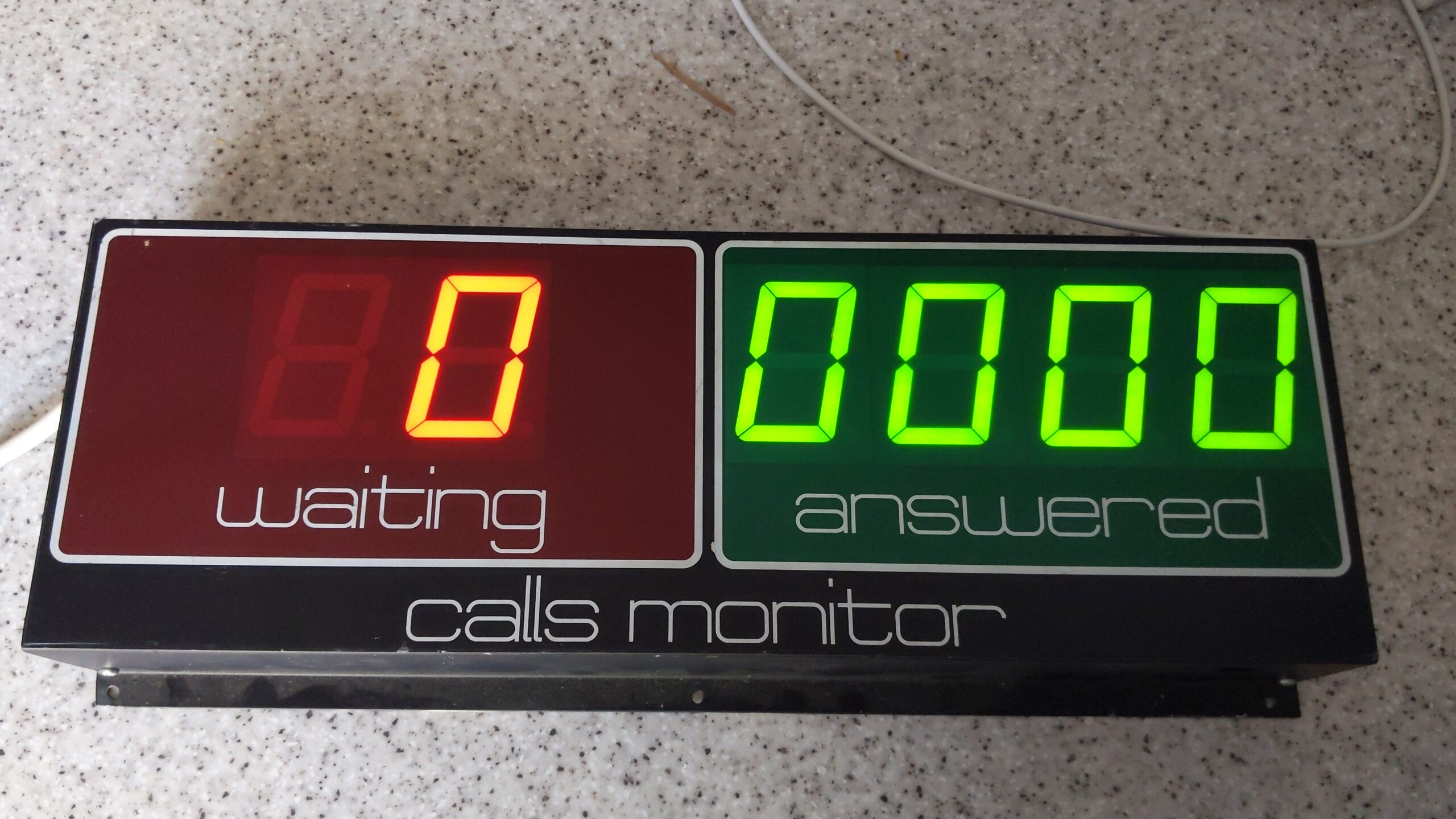
Another item I acquired was a calls waiting monitor featuring a 6-digit display. It comprised two red digits for calls waiting and four green digits for calls answered. Like the wallboard, this device employed an RS485 interface but this time controlled by a Philips 80C51 compatible microcontroller. However, I decided not to attempt to make it work and instead opted to salvage its parts. Inside, I found some 2.3″ 7-segment displays, which I have set aside for a separate project.
Unlike most other circuits using multiple 7 segment displays, the circuit design of the calls waiting monitor didn’t utilize shift registers to control the displays. Instead, it employed a parallel approach by sending the display data in parallel to several 74 series latches and then enabling the latch sequentially. For example, the data for digit 1 would be sent, followed by latching the output, then the data for digit 2, and so on. This method allows for updating individual digits without refreshing the entire display, which is quite efficient. However, it does require a significant number of pins on the microcontroller—14 pins compared to just 4 if using SPI with output enable connected to the microcontroller rather than tied to +5V.
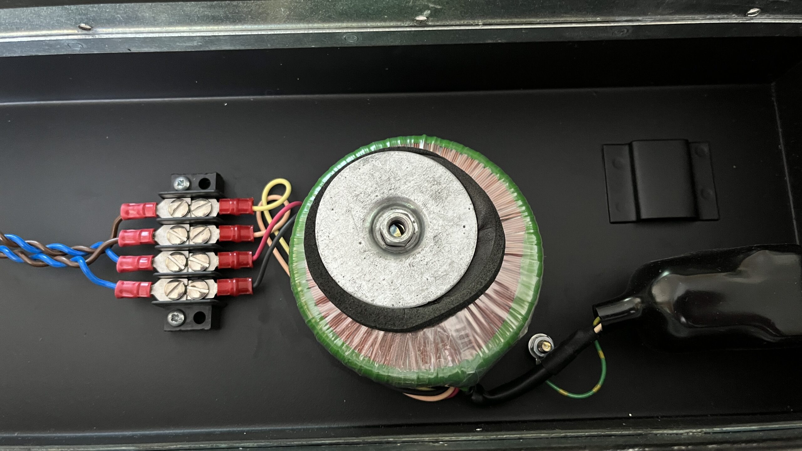
Interestingly, the calls waiting monitor utilized a 9V unregulated supply to power the LED display’s anodes. This supply was derived from two 9V windings of a transformer, passed through a diode from each winding, and then connected in parallel to the main supply rail. A 7805 regulator provided power for the microcontroller and the 74 series logic. Unfortunately, the unregulated supply led to uneven brightness among the segments depending on the number of segments lit, due to its lack of regulation. Additionally, the half-wave rectification method used caused a slight 50Hz flicker on the display. Although these design choices were not how I would have approached them, I presume they were the decisions of the original circuit designer.
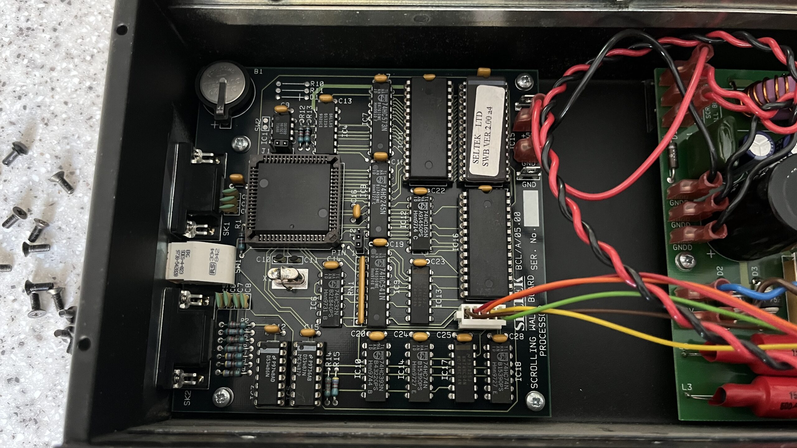
Finally, I attempted to read the contents of the 8051 microcontroller in the calls waiting monitor. Unfortunately, the security bits were set, preventing reprogramming or reading the chip. Although I initially considered reusing the microcontrollers since they were in sockets, I ultimately concluded that they were only suitable for disposal. On a different note, when I dumped the contents of the EPROM in the scrolling message display, I obtained interesting results but no clues regarding the driving mechanism. I did notice a self-test mode, but I couldn’t determine how to activate it. Speaking of self-test mode, the calls monitor had two jumpers that, when placed in test mode, made the displays scroll through the numbers 0-9 and letters A-F.
If you’re interested in seeing these devices in action & what components are inside in more detail, I have created a couple of YouTube videos on the subject, which you can find linked below.

