On one of my very old computers I had one of those LCDmodkit PC status screens that consisted of a 20×4 LCD housed in a 5.25″ bay and was interfaced to an internal USB header on the motherboard via a USB2LCD controller. As there are no Microsoft certified drivers available for this device it was no longer used in my newer Windows 10 or later machines. I removed the USB204B board off the back of the LCD and used the LCD for another project. That left me with a controller which was pretty much useless. On inspection I found it had an ATmega8 microcontroller and a bit of digging I found that this is based off the LCD2USB project by Harbaum (link to original project here) and it appears that the LCDmodkit controller is basically a redesigned original using SMT instead of surface mounted parts.
So I thought it is highly likely that the board could be reprogrammed and wasn’t locked. So I added a couple of headers to the former LCD connector and found, as in the schematic found on Harbaum’s project several of the I/O ports are broken out onto this connector. The rest are used for V-USB and serial and there is also a group of six solder pads labelled CN5 to the upper right of the microcontroller. I suspected this was for programming and poking around revealed this to be the case. The MOSI, SS and MISO pins were on these solder pads so I connected it to an arduino working as an ISP and uploaded a couple of basic sketches. Worked a treat but one thing to watch out for is the onboard crystal is 12Mhz not 16Mhz so anything that uses timers won’t work properly. However it’s great for very basic applications that involve sensors and activating outputs.
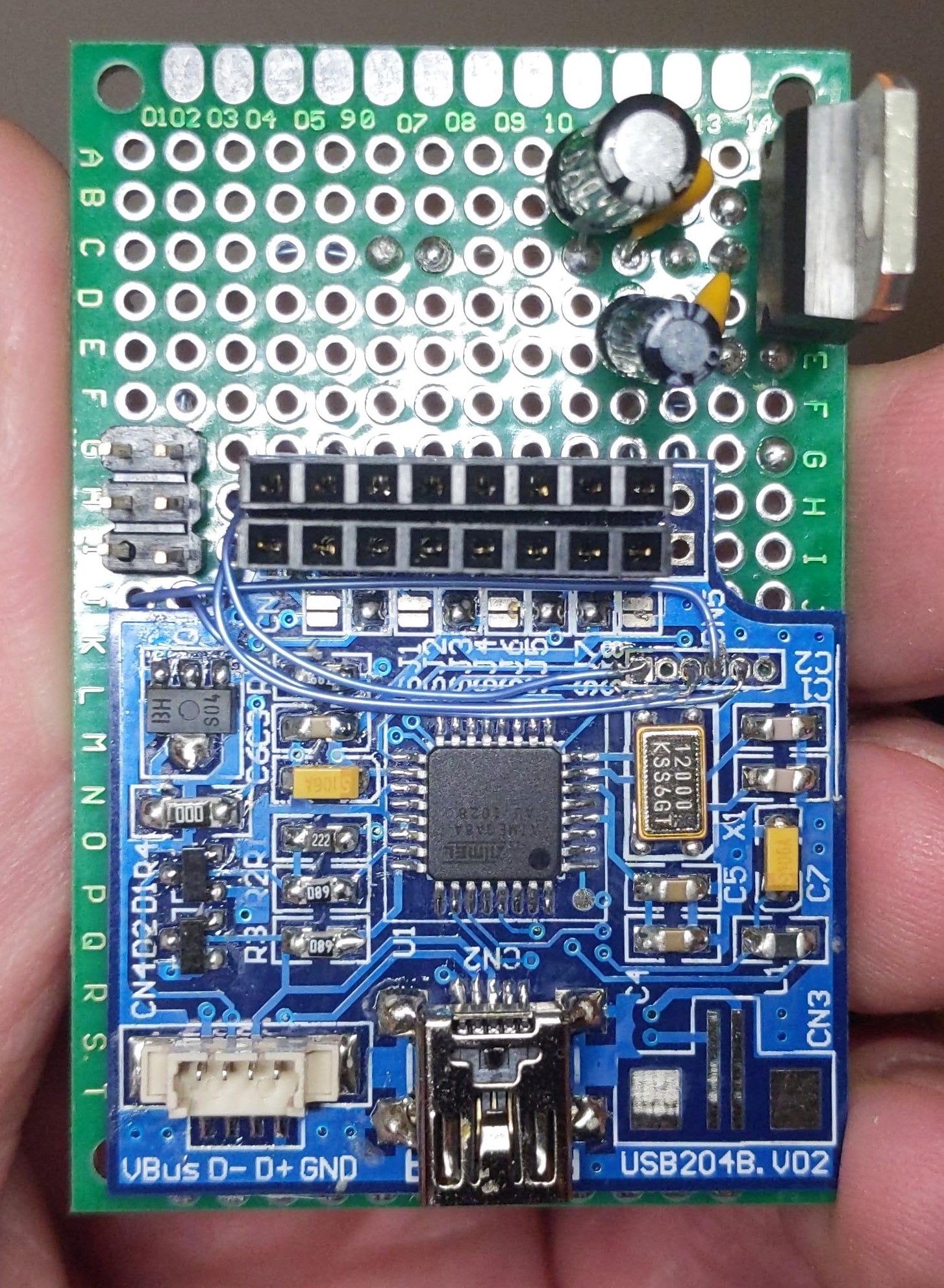
I’ve mapped out the six solder pads with pin one being to the right hand side of the photo. In other words pin one is nearest the edge of the board and pin six is nearest the microcontroller. I connected these via mod wire to a standard 6 pin ISP header on the perfboard.
Pins are 1= ADC6, 2= Reset, 3= MOSI, 4= SCK / SS, 5 = AVCC, 6 = MISO. 5V and power were taken from the 16 pin LCD header. The rest are easily found out by measuring continuity between each of the 16 pins and the pins on the microcontroller using a pinout as a reference. I used a 7805 regulator to power it but even if reprogrammed the original USB connector could be used to power the board.
So instead of having a pretty much useless controller worthy only of the bin I have a basic ATmega8 development board that I could repurpose into another project. At least it’s more useful than those crappy digistump boards. As for salvaging microcontrollers from electronics in general it’s a no-go as you will find they are usually obscure, not very hobbyist friendly micros and are almost always locked to prevent them from being reflashed or they are OTP only.
But if anyone has one of these old displays and is unable to use it, well now you can with a bit of patience. On a side note it looks like someone asked how to re-use this board back in 2009 on the Adafruit forums. Here’s the link for reference.


I did make a simple voltage monitor with this and I thought I’d post an update as I couldn’t get the pin mappings to work with the minicore boards. For example pin 3 should map to port D3 so you can in theory just declare pin numbers as you would do on an Arduino board. Setting a pin high or low didn’t do anything at all. I couldn’t get the analog to digital converter working either.
In the end I wrote it in “AVR C” and got rid of all the Arduino stuff and it worked perfectly fine.
Here’s the example code
2
3
4
5
6
7
8
9
10
11
12
13
14
15
16
17
18
19
20
21
22
23
24
25
26
27
28
29
30
31
32
33
34
35
36
37
38
39
40
41
42
43
44
45
46
47
48
49
50
51
52
53
54
55
56
57
58
59
60
61
62
63
64
#include <avr/io.h>
#include <util/delay.h>
float inVolts = 0.0;
float voltage = 0.0;
unsigned int adc_value; // Variable to hold ADC value
#define v_div 11.425 // adjust this according to actual measured value. 3.3M and 330K resistors used for divider.
#define v_ref 4.944 // replace this with actual measured VCC voltage. Cheap knockoff eBay 7805 low compared to known genuine ones which are generally bang on 5V.
/*
The voltage divider factor is calculated by dividing the first voltage by the second voltage or:
dividing factor = input voltage ÷ output voltage
For example, if the first or input voltage measured is 10.02V and the second or output voltage is 0.9V, then the division factor is:
10.02 ÷ 0.9 = 11.133
*/
int main(void)
{
DDRD |= (1 << DDD5); // set D5 as output
DDRD |= (1 << DDD7); // set D7 as output
ADCSRA = (1<<ADEN) | (1<<ADPS2) | (1<<ADPS1)| (1<<ADPS0); // Set ADCSRA Register with division factor 128
ADMUX=0x02; // set ADC input to port C2 (ADC2)
while(1)
{
ADCSRA |= (1<<ADSC); // Start conversion
while (ADCSRA & (1<<ADSC)); // wait until conversion completes
adc_value = ADCW; //Store ADC result
voltage = (adc_value * v_ref) / 1023.0;
inVolts = voltage * v_div;
if (inVolts >= 12.0) // show green
{
PORTD |= (1 << PD5); // set Green LED high
PORTD &= ~(1 << PD7); // set Red LED low
}
else if (inVolts <= 11.9 && inVolts >= 11.3) // show yellow
{
PORTD |= (1 << PD5); // set Green LED high
PORTD |= (1 << PD7); // set Red LED high
}
else if (inVolts <= 11.2) // show red at 2.8 volts per cell
{
PORTD &= ~(1 << PD5); // set Green LED low
PORTD |= (1 << PD7); // set Red LED high
}
_delay_ms (10); // wait for ADC to settle between readings
}
}