I posted back in January about a project I had in mind for our battery charging area at work to automatically turn off the power to the battery chargers if dangerous levels of toxic Hydrogen Sulphide were detected. The project was cancelled but resurrected about 3 months later when another battery failed releasing gas and we looked at this project again and decided it was a good idea to try building it.
So for the last two months I have been testing it and found that being based on a cheap MQ-136 sensor (good quality H2S sensors are very expensive) it performs reasonably well. With such a cheap sensor accurate readings of H2S are not really possible but it does detect gas and turn off the power which is exactly what we wanted it to do.
The project is based on an arduino as the controller with warning / status messages displayed on an LCD and gas level from 1-9 shown on an LED display. An alarm sounds when dangerous gas levels are present and the power to the chargers is turned off.
Basic summary of operation
The Hydrogen Sulphide gas is detected by a MQ-136 sensor which is specifically designed to detect this kind of gas rather than similar sensors (such as the MQ-135) that detects a few different types of gas. This is fed into the ADC of the Mega 328 controller and the software monitors the analog value and triggers events if thresholds are met.
There is a 20 x 2 LCD that displays status messages such as when operation is normal or if gas is detected and the status of the charger power. A 7 segment display shows the gas level on a scale from 1-9. If gas is detected above a certain threshold the warning LED lights and a piezo buzzer emits a loud, shrill sound to get attention. At this point the relay which switches the power off is activated. A 3PDT relay is used with the power on the normally closed contacts so that the unused normally open contact could be connected to an extractor fan at a later date.
When the gas level returns to normal, the LCD shows that it has been tripped and the elapsed time since the last alarm. The power to the chargers will remain off and the buzzer will continue to sound until reset. This will give basic protection from a faulty battery giving off gas by turning off the power. The relay could also be connected to an extractor fan to vent the gas outside.
The circuit, PCB and case
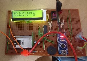
As you can see here is a photo of the PCB built on veroboard with the current status as normal. The 10 on the LCD is the raw analog value and the 7 segment displays shows a dash (no gas detected) with the warning LED to the right off.
Power is supplied to the board from a switched mode power supply dropping the mains voltage to 12V which is then fed into a 7805 LDO regulator for the supply to the microcontroller. The LED display is a high brightness module which needs 20mA per segment which would be too much for the Mega328 to supply if displaying a number 8 so I used a ULN2803 to drive the segments supplying the 7 segment display from the 12V supply via suitable resistors.
The LCD is a i2C module rather than parallel so that it frees up the micro’s pins to drive the display and relay. A buzzer and transistor switch to drive the relay completes the circuit.
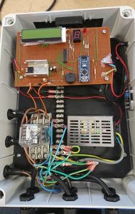
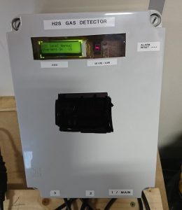
The final project was mounted onto a plastic sheet and built into an electrical junction box with a cutout made for the display and a cooling fan at the top. The three power inputs and outputs can be seen at the bottom of the case. Fuses are provided for fault protection on each of the three relay outputs.
As you can assume the relay used has three independent contacts with a single coil so that load for the chargers is split. We have 8 chargers plugged into each output. The inputs are plugged into individual wall sockets so that AC current for all 24 chargers are not connected to a single AC wall outlet which would overload it.
Here are the schematic diagrams, code and the datasheet for the LCD module used which is based on the ST 7032 controller so you will need the LCD_ST7032.h library.
Library for Midas displays LCD
Testing and notes about accuracy of the MQ-136
During testing I found that the ‘burn in’ of the MQ136 sensor is a heck of a lot longer than the 24 hours the manufacturer recommended. When the sensor was new the no gas present analog value was around 10 and rose to 15 after 24 hours. However I noticed that the analog value kept rising over the following days and it depended on the room temperature.
I thought my sensor was faulty but a bit of research shows that if the sensor has been stored for a very long time (over a year) it can need up to 2 weeks to burn in before the no gas analog value stabilizes. This certainly was the case with mine; with a room temperature of 21 degrees C with no gas present the analog value was between 39 and 45. As the room temp increased to 30 deg C the value went up to nearer 60 so the sensor shows significant drift making it difficult to calibrate.
As you can see the MQ136 is temperature sensitive which in our application isn’t ideal but I could work around that. When the sensor was put near a source of H2S the analog value shot up to 600+ so thresholds for the LED display could easily be established as was the value for the dangerous level where the power would be turned off and alarms sounded.
So final thoughts. Was this a successful project? Almost certainly; it cuts off the power if toxic levels of H2S is detected and informs me when it was detected. It won’t win any accuracy awards and it is very difficult to calibrate these cheap sensors. If accuracy is desired a more expensive sensor should have been used and a calibration routine in the code run. However I didn’t need that. I’m a bit dubious that the MQ136 can be powered 24/7 for more than a year without loosing it’s detection ability or the heater burning out but I guess time will tell.
For now this is a cheap way of automatically powering off a battery charger when left unattended if the battery decides to fail and vent.

