I’ve been using the Arduino for a while now and made a few projects but at work we use the 8051 as the primary micro for our in house equipment. Yeah it’s outdated but Silicon Labs have taken the original 8051 design and vastly improved it with clock speeds of 100Mhz. It can easily outperform an Arduino and technically is a more capable processor.
However support is limited and its for professional programmers only whereas the Arduino is more for hobbyists. Knowledge of the CPU and in depth knowledge of C is required to get anywhere with this. I decided to buy an Atmel version which is more or less based on the original Intel design but it does run at 24Mhz. It also comes in a DIP package too so is ideal for breadboard and veroboard projects.
I found that development kit and software was expensive unless you used the outdated SDCC compiler or BASCOM. Support was lacking and I struggled to make anything useful with it. Compared to the Arduino with it’s libraries etc you don’t need to know how the AVR chip works and there’s loads of help out there.
So I decided to cut my losses and restrict 8051 development to work with the more capable Silicon Labs chips. But what to do with this chip? Well I needed a new bedside clock. Bingo I found a pre-compiled .hex file I could load onto the chip and accompanying schematic here http://www.8051projects.info/threads/microcontroller-based-digital-clock-with-alarm.541 Looks easy enough to make. It just needed a few modifications.
The circuit does not use an RTC and instead relies on the micro’s own internal timer to keep the time. There’s no facility for it to keep going should there be a power failure so I decided to add one. Unfortunately I wrote the modded schematics down on paper and then binned them once the project was complete but I can pretty much describe my mods. Here’s the original circuit:-
What I basically did was to use a relay with normally open contacts in series between the anode supply to the LED modules and microcontroller. The relay coil was energised when the power came on from the unregulated 12V input. A supercapacitor was used between the micro’s 5V pin and ground pins supplied via 100 ohm resistor to limit current surge at power on. A diode bypasses the 100ohm resistor feeding power back into the micro. I used a Schottky diode to reduce voltage drop. To put it into simpler terms when the power was off the relay was open and the micro’s 5V pin was only connected to the supercapacitor via the diode. It was disconnected from the supply coming from the regulator. The LED module anodes were on the regulator side of the relay contact.
This worked well in practice and gave around 10 mins backup time. A reset switch was added on the rear as the micro crashed when the voltage fell below 4V but not low enough to do a power on reset once the power came back. I also added a night light too.
Programming the AT89S52 (8051) microcontroller
It seemed you needed to purchase an expensive programmer for this but wait; couldn’t an Arduino do this? the AT89S52 is programmable by SPI after all. It turns out there is a sketch that does exactly this. Turns your arduino into an 8051 programmer. All I had to do was connect it up and download the .hex file onto the chip using a program I found on the internet. It isn’t made by any named company just named ‘8051 SPI programmer’
It took several attempts to program the chip. The reset on the 8051 is active high; opposite to the AVR and it must be held high during programming. Eventually I was successful and the project was assembled onto veroboard.
Testing and final thoughts
The clock keeps good time gaining about a minute a month. The clock has one annoying feature that my previous clock did; the alarm does not auto arm for the following day. You have to turn it off then back on again for it to shut up. This is done by a ‘double click’ of the alarm set button. As there’s no hardware or software debounce this can be frustrating and when setting the time you can easily skip past the numbers you wanted. Source code is provided to change this but it is written in basic not C or C++
I found the alarm to be too quiet as well and amplifying it was without much success. I didn’t really want to bother altering the source code to rectify these annoying niggles and decided to use it in the living room instead. I don’t use the alarm feature.

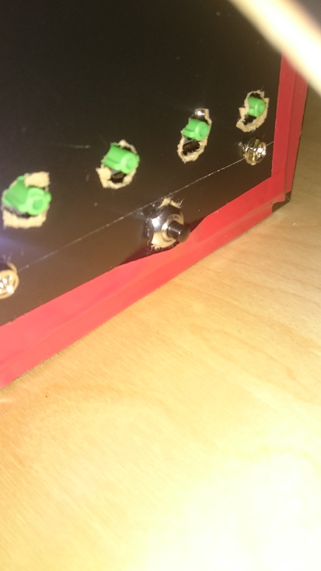
Here’s the final product housed in an Ikea photo frame. Semi transparent stick on vinyl was used over the glass on both sides to hide the PCB and a cutout was made on the back side to allow the LED display to shine through. It looks quite modern and stylish and I’m quite pleased with it.
The rear is stuck on with sticky tape though as the frame wasn’t quite deep enough. You can see the buttons sticking through the back cover.
All in all a pretty successful 8051 project but I won’t be bothering with this micro again and will continue to use the Arduino instead.
Here’s the project notes and source code if you want to try it yourself. The final version used a larger supercap (2.2F) and provided around 10 mins of backup time. Enough for those mini blackouts or power sags I’m getting more often than I deem normal. I used a 12V regulated supply in the end from a wall-wart.
And finally some eagle schematic and PCB layouts (needs finishing off, autoroute didn’t quite work) 8051 Clock Eagle Files
Final note: if you do want to make this project please see the original link on 8051 Projects as there’s much more information on there. I wouldn’t bother posting on the forum as the last post was in 2014. What it does not tell you is the 8051 chip can either be an 89C51 / 52 or 89S51 / 52 (the latter preferable as they are SPI programmable) and the crystal must be as specified. Using the wrong micro or crystal will result in a non working or inaccurate clock. The difference between the ’51 and ’52 is the flash and ram size. Either should work but I used an 89S52 which has 8k flash and 2k ram.
The LED displays must be high efficiency modules and current limiting resistors should be chosen to pull no more than 2.5mA per LED segment. I used 1.2K resistors with 0.3″ high displays which give around 300ucd at 2mA. Failure to do this will either result in a dim display or your will blow up the microcontroller. The 8051 is NOT a modern micro and cannot source / sink nowhere near what an AVR or PIC can.