In the quest to make something useful out of a load of old junk I’ve found in my cupboards I came across my old clock radio I’ve had since 1978 a while back and decided to do something with it rather than throw it out. It actually worked but it had an ‘accident’ with the floor a few years ago which had broken the casing and cracked the main PCB.
I have no idea why I just didn’t throw it out then but I had replaced it with a cheapo clock off ebay which projected the time onto the ceiling with some superbright LED’s and mini LCD’s. Quite innovative but that piece of crap lasted a few months before breaking prompting me to replace it yet again. Well the second replacement failed by randomly corrupting the display and resetting itself. Not ideal if you want to set up an alarm that can reliably wake you up. Acctim? Craptim more like.
On one of my earlier posts I made an alarm clock using an 8051 microcontroller but the alarm was unsatisfactory so in order to avoid more cheap Chinese electronics that doesn’t work I decided to make something out of what remained of the 1970’s alarm clock. The clock PCB was functional as was the LED display but it was very dim and had small segments. It also drew a lot of current (nearly 600mA) and the clock IC, TMS1944AN2L got very hot. I had a Fairchild Semiconductor FCS8000 LED module which is also 1970’s vintage salvaged from another clock but I had a datasheet for this which showed that it is a low current, high brightness module. It draws much less current (and has a bigger display) than the old LED display.
With that sorted the next thing I did was to find a datasheet for the TMS1944AN2L which turned up no results on Google however I did find out it has the same pinout as the NTE2061 but this ‘equivalent’ functionally is slightly different. The only difference I can find is that the TMS1944 has seperate buttons for hour and minute set whilst the same pins function as fast set and slow set on the NTE2061. Another equivalent is the MM5387 although this is an equivalent of the NTE2061. Supplying power via the original transformer fed into a rectifier proved this to be the case and the clock worked.
So I set about replacing the display with the higher brightness and low current module which needed a higher value current limiting resistor of 50 ohms over the 10 ohms of the original circuit. The FCS8000 module has a common cathode pin for all segments so the current limiting resistor was put between this and ground as in the original clock. This was a success and now the clock draws around 150mA with the chip getting only mildly warm. Much better for power consumption and no worries about it going up in smoke. 🙂
I also pulled apart the original green LED module and was surprised so see that it used tiny SMD LED chips soldered to a PCB which was then covered by a piece of plastic casing with the segment cutouts. A diffuser / lens stuck over the top completed the module. I didn’t think they did SMD back in the 70’s.
Building the power supply board and adding an alarm circuit
The clock chip uses the mains frequency for timing and this was supplied from one of the AC wires from the main transformer via a 100K resistor. All I had to go on was the typical application circuit found on the NTE2061 datasheet. I didn’t have a datasheet for the TM1944AN2L so I assumed it would work which it did with no problems. However the datasheet does not make it clear how the alarm output of the chip drives an external sounder for the alarm so I had to guess.
A frequency counter revealed it just outputs a continuous 100hz signal when the alarm is going off so I fed this into a discrete emitter follower transistor audio amplifier circuit built onto the power supply board. Some experimenting with component values (the IC output needed to be AC coupled) I had a usable alarm circuit. I used a passive magnetic buzzer for the sounder. Unfortunately like most alarm clocks the alarm does not auto arm for the following day. You have to press snooze to shut it up then turn off the alarm and turn back on again or just simply turn it off and on again. I wanted to just press the alarm stop button and forget about it till the following day. No matter, it would have to do.
The case and adding temperature display
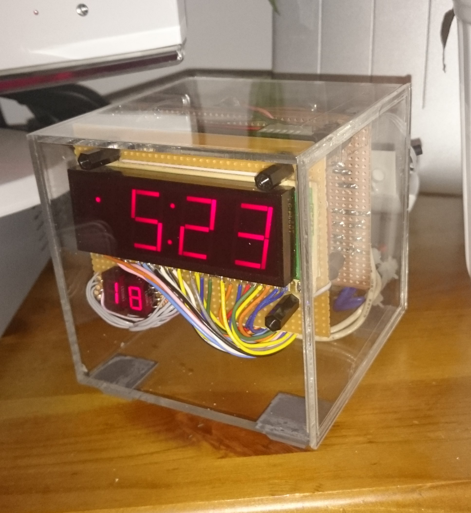
I needed to re-case it as well so looking round on Amazon and Ebay I found a great perspex cube that would make an ideal case. I went for transparent to avoid having to cut holes for the display and it also shows off the inside which looks cool.
I had some spare space on the PCB as I had cut them to the same size as the case interior so it would be a perfect fit so I decided to add a digital temperature display using the same design as a previous project featured in an article about fake DS18B20’s just for the sake of it really. As the DS18B20 was fake it produced readings about 2 degrees higher than it should so some code modification was required to compensate for this.
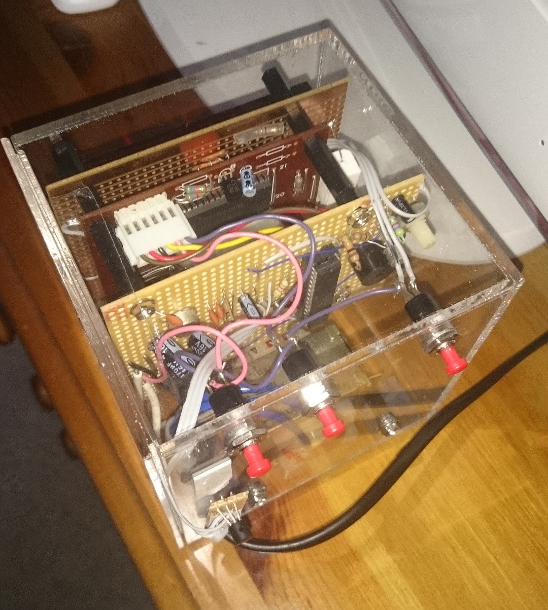
The mains transformer was mounted at the bottom of the case with the PCB’s fitting neatly above and held in place by support pillars. The temperature sensor was moved outside of the case so the heat from the electronics would not give false readings. The DS18B20 is very sensitive and heat conducted through the connecting cable will affect it’s reading.
All in all, it’s a success and it’s sat doing it’s duty on my bedside cabinet. Accuracy isn’t too bad but it relies on the mains grid frequency so it can be some several tens of seconds slow / fast varying from day to day. Overall though these type of clocks maintain good timekeeping unlike crystal oscillator based clocks which slowly gain or loose time over a period of time. Timekeeping obviously relies on the quality of the crystal used and far eastern cheap brands leave a lot to be desired. A good brand quartz crystal clock though is perfectly fine.
The next thing to add is some blue LED’s to light the interior of the case so it looks cool. It will do for now till I make something better which of course will be Arduino based.
Finally here’s some scribbled notes made during the construction of the project which details pinouts and design notes plus any mods I had to do.


