***Updated*** now version 5 which has a vastly improved display layout and better voltage reading accuracy. Download can be found towards the bottom of this page.
During my clearout of old junk I came across an LCD display fitted into a small plastic case with a PC parallel cable attached which was originally used for a PC status display using LCD smartie. This was used on my old, old, PC (Pentium 4) to display system status messages and music track info from winamp.
As my new PC lacked a parallel port (yeah I could have added one but no PCI slots, just PCI-E) this was relegated to the junk cupboard. So what shall I do with this display and case?

Well I have a pile of rechargeable AA batteries of various ages and I came across this Arduino based battery tester which looked ideal to test said batteries. Now it just needed a few simple modifications; I added an LED that flashes to get attention when the test is complete and changed some of the screen messages. Simple stuff. After all I was just starting out with the Arduino and I felt this was a great starter project.
I managed to cram a small PCB containing the switching FET and an Arduino nano into the case. 3M double sided sticky tape came in handy here 🙂 I fitted a battery holder over the hole where the parallel cable previously exited. The unit is powered by a Nokia phone charger as the circuit draws around 60mA and even with this load the supposedly 5V output of the charger was 8V; ideal for the onboard regulator of the Nano.
Well, it works. The circuit puts approximately 500mA load onto a battery so an average NIMH rechargeable battery takes around 4 hours to discharge to 0.93V which is the cut-off voltage set in the software. Any lower would damage the battery by over discharging it. NiCAD batteries can also be tested in theory but I’d advise against it as most of these have a low mAh rating; typically 600 or so. This tester puts too much load onto them resulting in the battery getting warm and giving a lower than expected capacity rating due to being discharged at a rate of discharge higher than the battery was designed for.
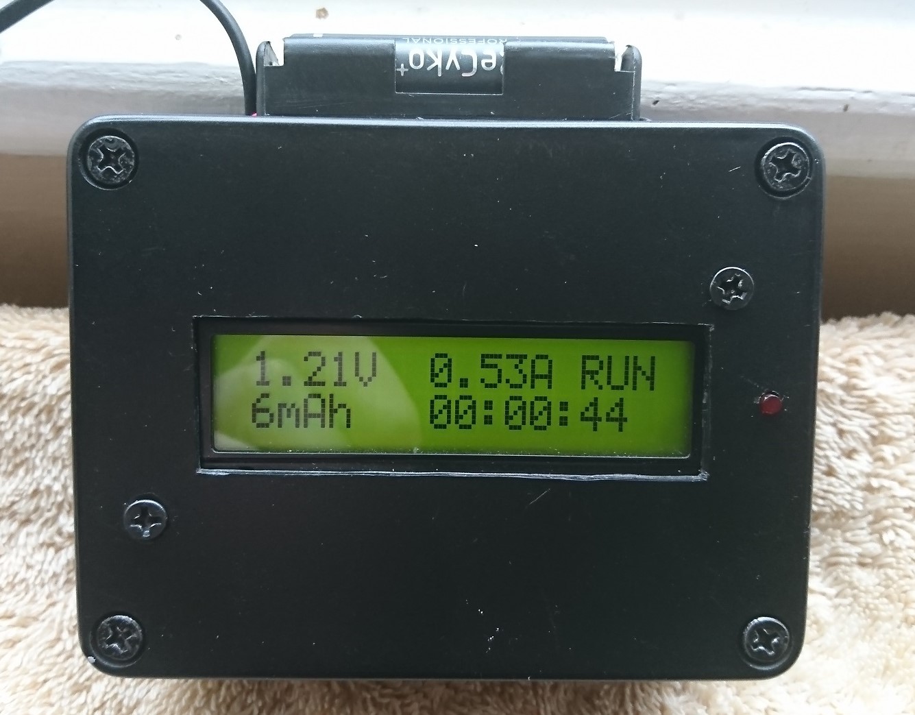
It’s not brilliant as it does not apply a constant current load; the 500mA is only at a voltage of 1.3V but it gives a reasonable representation of a battery’s condition. Easy – if you have several batteries of the same type all fully charged and one lasts 4 hours and one lasts 2 then the latter is weak and should be replaced. The tester displays current voltage, elapsed time in minutes and the mAh rating which increments with elapsed time. The counter stops when 0.93V is reached and the resulting mAh rating plus time is displayed.

A few words on the components used should you decide to make this project. First of all the switching FET must be able to be fully saturated (switched on) at 5V so a logic level FET is required. A heatsink isn’t required as the internal resistance of the FET is very low and all of the energy is dissipated in the load resistor which should be rated at 5 watts ceramic or wirewound type. A 2.2 meg ohm resistor was also added from the sensor input pin to ground as I found that the battery tester would start randomly when there was no battery inserted. This is explained in the notes downloadable along with the modified code at the bottom of this post.
With some small code modification this can also test lithium cells but I didn’t bother with that. You will have to adjust the calibration quanta and cutoff voltage plus max voltage in the code to match the higher nominal voltages. You will also need to change the AREF to 5v (vcc) instead of the 2.5v or so as in the original design. This tester cannot measure voltages higher than 5V (in fact this would blow up the mega 328) so it is limited to single AA batteries (technically a cell) and single cell lithium LIFePO4 / LiPO / Li-ion batteries up to 4.2V. For higher capacity cells you may have to adjust the load resistor value as well according to ohms law and the suggested rate of discharge of your battery. As a general rule 500mA is pretty much suitable for most modern batteries.
I will design a better one someday as only being able to test one is a bit of a problem. Waiting 4 hours for each battery when you have a lot of them can be a pain. The time is also displayed in minutes; it would be nice for it to change to hours elapsed after 60 mins but it does not. However it isn’t hard to work out that 246 mins is 4 hours and 6 mins elapsed. It just would be nice if it were clearly displayed. A further modification would be to ditch using a resistor divider to provide the reference voltage and use a precision reference chip such as the LT1009CZ which gives a 2.5V output; perfect for this project. This would give more accurate readings but really this project is about finding a dud in a pile of batteries.
Downloads
12 volt sealed lead acid tester version (has been tested and works) schematic & code
Latest updates and code version
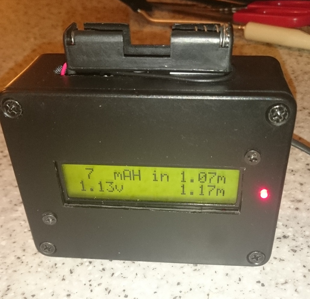
Update March 2019 – I have since updated this project so it produces more accurate results and changed the display layout. I used a TL431 2.5V reference IC as the voltage reference as the previous method of using a voltage divider with the 3.3V supply was too unstable. I have also improved the display layout and added an elapsed time display in hours, mins and seconds. It’s still not going to be 100% accurate as it does not measure the actual current drawn but this tester was really built to provide compare runtime between batteries with a given load. The approximate mAh rating is a bonus.
Bugs and issues:-
If you notice the test restarts (or it won’t start at all) you may need to experiment with the sensorvalue in this line of code:-
if (!batteryIn && (sensorValue > 491)) – this is around 1.2V
On the test display screen if the total mAh rating is over 999mAh it will push the ‘h’ off the display. To avoid this you could replace the word capacity with rating, use a bigger LCD etc. I only noticed this small error when I ran a full test on a battery but it’s not worth re-uploading a newer version. This is something that is easily fixed in the code.
If thin wires and / or poor battery holders are used you may see a voltage drop of 50mV or so between the battery contacts and the Arduino. Use good quality battery cable and holders to minimise this issue. Also pay attention to ground connections and use decoupling capacitors accordingly. The TL431 reference chip absolutely must have these capacitors & a current limiting resistor for it to work correctly to avoid damaging the TL431 and Mega328P. Refer to the datasheet for the TL431 for further information. Link to the TI version which I used is here. http://www.ti.com/lit/ds/symlink/tl431.pdf