
This project came to being when I wanted a large multi digit 7 segment LED display but I was only able to find MAX7219 or similar based display boards with digit heights up to 0.56″. Not being able to find what I wanted, I decided to make a 6 digit clock (one of my earlier projects) and as I had some larger 2.3″ displays spare I designed another 6 digit display this time with just the SPI interface so it can be connected to any microcontroller with a SPI interface.
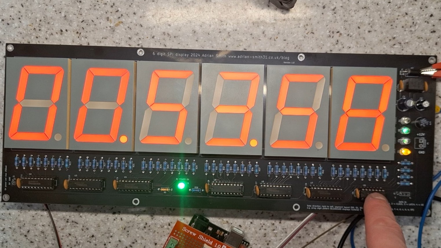
To keep costs down I decided against using external drivers with a MAX7219 and instead went with a chain of shift registers using TPIC6B595’s as their open drain outputs can sink up to 500mA (shared between all 8 outputs) and up to 50V – ideal for the large LED displays that have a forward voltage of 8.4V. The PCB would have to be powered from 12V due to the higher voltage displays so a 7805 regulator provides the 5V power for the shift registers and the input buffer which also translates 3.3V logic levels to 5V required by the shift registers.
The board is suitable for electronics hobbyists and it provides ultra bright LED’s o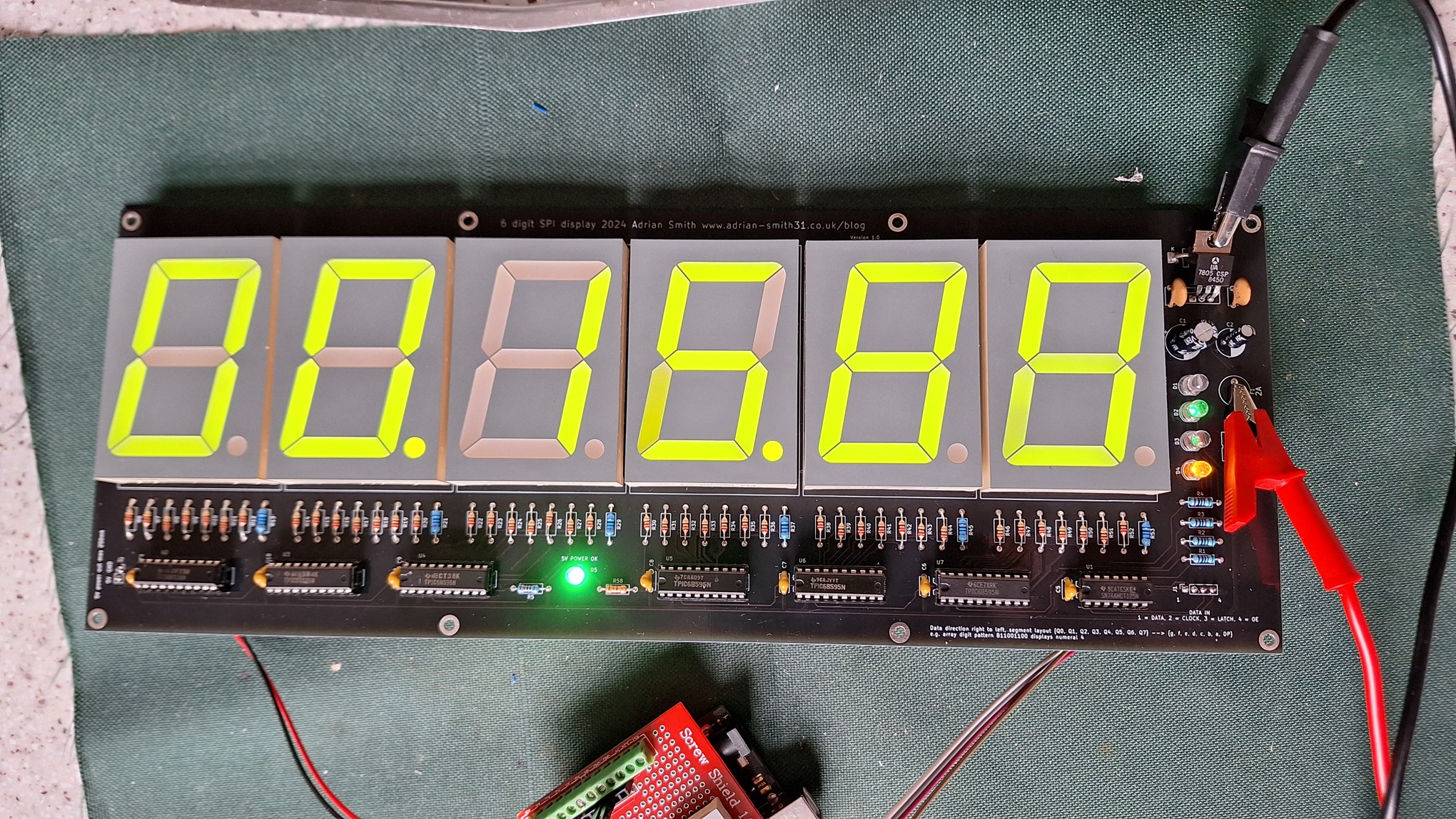 n the data input lines to indicate input signal status. With input signals that have a very low duty cycle the status LED’s would not light hence why ultra bright LED’s were used. Ideal for testing and development use and for use in a final, one off project. It runs off 12 volts and has an onboard regulator for the IC’s. It is compatible with 3.3V and 5V logic level inputs on the data connector.
The board was also designed with through hole components for ease of assembly and features a reverse polarity protection diode and a 5V output for powering an Arduino or similar. Current consumption with all digits and segments on is around 700mA. A 12V regulated power supply rated at 2A is needed to power this board.
I will be selling these on eBay as I build them and also maybe as kits – please see my listings to the right.
This project was sponsored by NextPCB.com who kindly made the PCB’s for them. They are good quality and are made with black soldermask. As this project is no longer being made by me and sold on eBay I have released the Gerber files.
SPI Display Board Instructions
YouTube video


Hello, 1 year ago we purchased two 6-digit red displays.
After a year, our customer sent us back our game (which used the two displays) saying it had been broken for several months.
He sent it back for repair.
The two displays have broken segments in four of the 12 displays.
We’ve been looking for an explanation for the broken displays.
We’ve read the datasheet for the TPIC6B595N component.
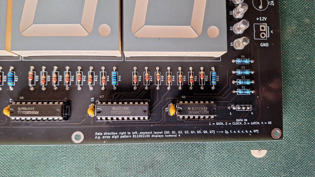
We’ve noticed that the resistor values are different from those mounted on the board.
We believe you sent us boards with the wrong resistors.
The resistors are some 220 ohms and some 22 ohms, as you can see from the photos I can provide.
We need to know if it’s true that this is a mistake.
How I can send the photos?
Best regards
Animatrix
Giampiero
Hi Giampiero,
I have reviewed your photos you sent. Unfortunately those are not in the same condition they were sent in. You got one red and one green display – you photographed 2 red displays. The 22 ohm resistors fitted to the boards have clearly been replaced as the soldering is blobby and clearly shows signs of rework. I have sent you photos of the boards as they were sent to you.
The 22 ohm resistors should be 220 ohms although it looks like the LED modules have been swapped out too so you would need to check to see if 220 ohm is suitable for the displays you have replaced them with.
The boards in your photos are not the same boards I sent you or they have been heavily re-worked. The 22 ohm resistors in your pictures were not fitted to any of the boards I sold so the mistake is not on my part. Your customer or someone else has incorrectly replaced the 220 ohm resistors with 22 ohm. Not my mistake – the LED segments would have burned out almost immediately if I had fitted the wrong ones.
Best regards,
Adrian