I have some largish 7 segment displays which are 0.8″ in height but I found that they were dim when driven from a MAX7219 even at full brightness. I found that this was because the LED displays I were using need around 15 mA for a decent amount of brightness, 25mA ideal. However the MAX7219 only has a maximum peak current of 40mA per segment; now that is peak current so that means with a multiplexed display that will be divided by the number of digits to give an average current of 5mA, or if you prefer the equivalent DC current. Now as my displays need 15mA that simply isn’t enough hence the dim display.
So to get around that problem I used a UDN2982 as a source driver between the segment outputs and the LED segment anodes. 47 ohm current limiting resistors were used (more on that later) and a ULN2803A was used as the sink driver on the digit outputs. Now as the digit outputs will be at a logic low level I had to use an 74HCT04 inverter between the MAX7219 and the ULN2803A as the ‘2803A needs a logic 1 to ‘turn on’ it’s outputs.
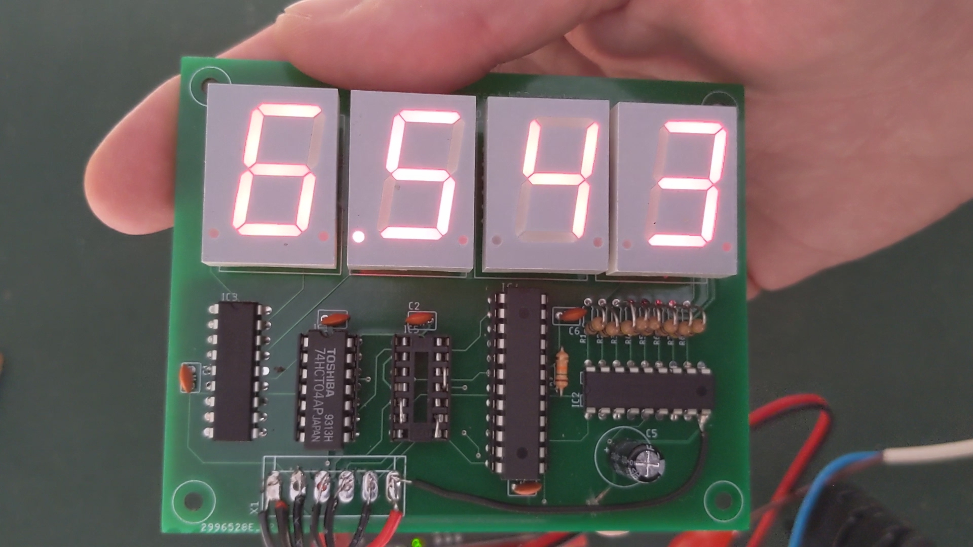
I used an LED supply voltage of 7V as 5V wasn’t enough to get a decent amount of current through the displays as the UDN2982 drops about 1.6V across it and the ULN2803A about 1 volt. Together with the voltage drop across the LED display I was only left with 0.4V to play with at a supply voltage of 5V. Both the ‘2803A and the ‘2982 have a absolute maximum current of 500mA for the entire chip so I aimed for 60mA peak current per segment which gives an maximum current through the UDN2982 of 480mA when the worst case scenario of the displays showing 8 and the decimal point is lit. 60mA divided by 8 digits still only gives 7.5mA average segment current – still not enough but as I was using only 4 digits I set the MAX7219 scan limit to only 4 displays which doubled it to 15mA equivalent DC current. This resulted in an acceptable display without overloading the driver IC’s. I did try it on 5V with 6.8 ohm resistors giving around 7mA current but it didn’t work.
You may ask why didn’t I just use the MAX7219 and set the scan limit to 4 displays? Well to answer that it could blow the MAX7219’s outputs as they would be overloaded and it would still only result in a DC equivalent current of 10mA. With it only driving the base of a transistor at a low current rather than LED’s it will not kill the chip. This is explained in the datasheet of the IC.
With this setup the current limit resistor of the MAX7219 can be pretty much any value (Maxim recommend 47K) as the chip is not directly driving the LED’s anymore; it is driving the UDN2982’s inputs which need a few mA of current to switch on. They have integral base resistors so there is no need to add any after the MAX7219. Display brightness can still be controlled in software as the software control adjusts the duty cycle of the multiplexing thus dimming the display as the segments are lit for a shorter period of time. The external resistor on the MAX7219 sets the maximum current provided by the integral constant current drivers.
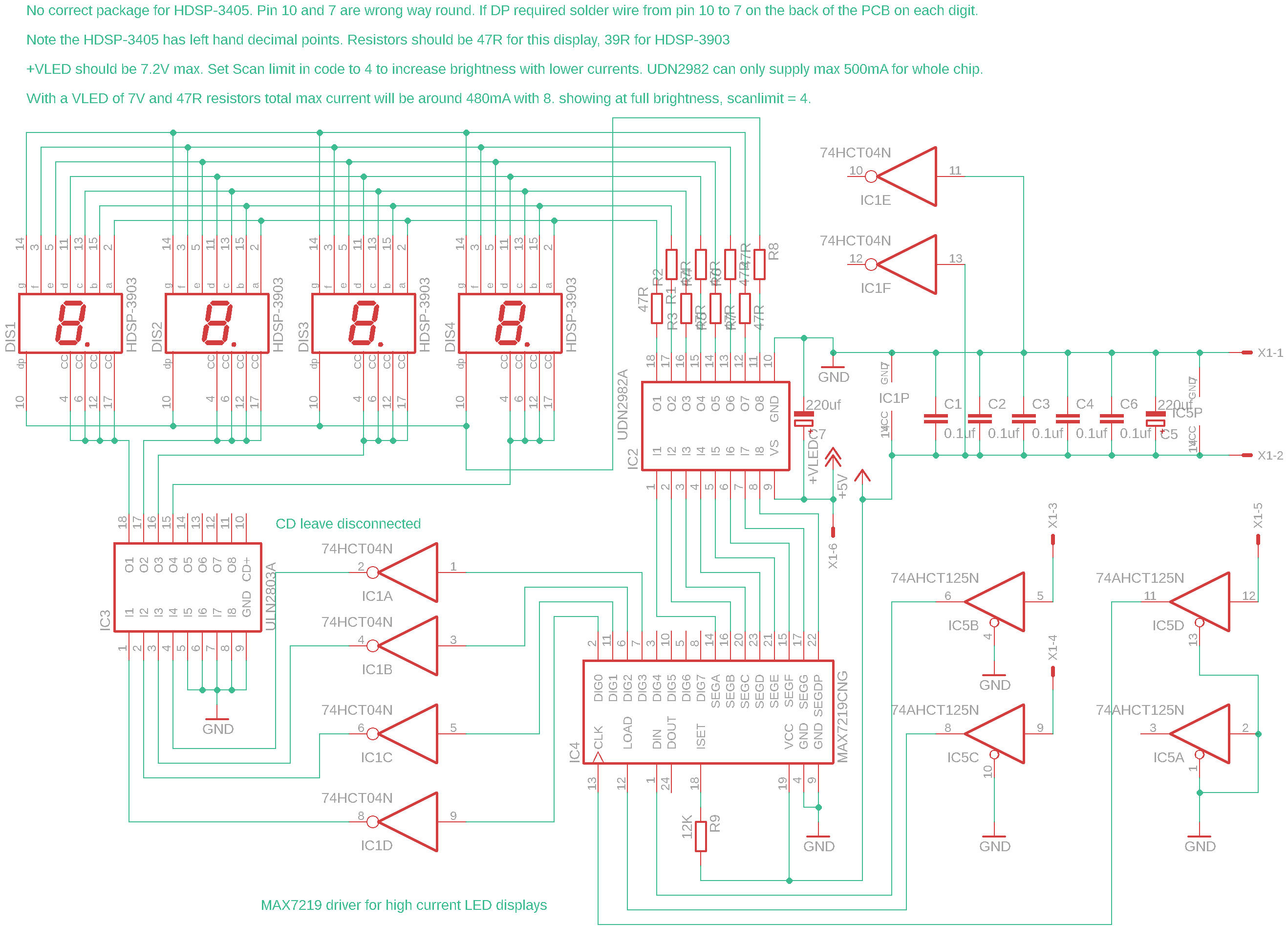
I made a video on it which I will post below which shows what I mean in more detail. The example circuit below can be modified to suit your particular displays – any large 7 segment display could be driven as long as the segment LED’s are in series and the V-LED voltage is increased to compensate for the number of LED chips per segment. Also the current limiting resistors will need to be adjusted too accordingly. Also watch out that you don’t exceed the maximum power dissipation for the UDN2982; it produces 65 degrees C of heat per watt. That can be calculated by peak current per segment x 8 segments (including DP) x voltage drop across the UDN2982. In my case that is 0.057x8x1.6=0.729 watts.
Example schematic
Note: 10K pullup resistors may be required on the four inputs to the 74HCT04 depending on if you use a genuine MAX7219 or a clone. I missed that one but my example circuit works fine without them. Unused inputs must be tied to ground or VCC as per the schematic. Decoupling capacitors are very important and must not be omitted.
Youtube video

