I’ve been working on a new Arduino project; the ultimate alarm clock which shows the time and date on a 16×2 LCD module and features multiple alarms with repeat / auto arm and radio function. I used a Tiny DS1307 RTC and EEPROM module which is a breadboard / veroboard compatible PCB containing a DS1307 RTC chip and a 24C32 i2C EEPROM. There is also a place for a DS18B20 thermal sensor but mine did not have this installed.
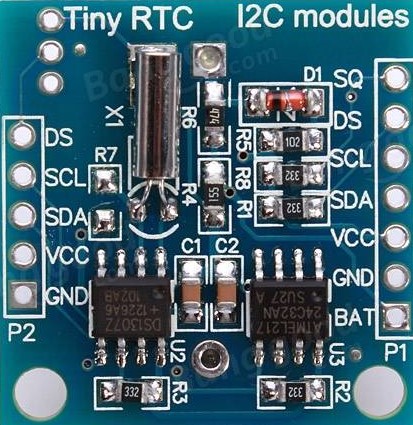
The clock functions great but I have found that the RTC module gains time about 6 seconds a day. This is due to a number of issues; the quality of the crystal used, the position of it on the PCB, the value of the load capacitors and it’s questionable if the DS1307 is a genuine Maxim chip or not. The module came from Banggood (China) at a cost of only a few pence of the chip itself (in bulk) so who knows.
The DS1307 is not known for it’s accuracy though; the DS3231 is a better choice if you need accuracy as it works with the basic functions of the DS1307 libraries. It just lacks some features such as onboard NVRAM. As I needed to use this NVRAM to store alarm settings etc I had to go with the DS1307 and write some code to halt the Arduino for 6 seconds then write the time back to the DS1307 minus 6 seconds. This should work in theory bringing the accuracy in line with the DS3231 and DS3232 RTC chips.
I have been testing it for a few days and I can now post the rest of the project details.
I have built a couple of clocks one based on an 8051 and one using parts salvaged from a couple of 1970’s clock radios which both work well but they lack a repeatable alarm and the ability to set multiple alarms on specific days which I would consider a must have. I did a bit of research and came across an example clock for an alternative to the standard DS1307 library. The clock code is fully functional and uses a parallel 16×2 LCD module for the display. So of course I decided to build it.

Modifying the demo code to correct time drift
As in the intro above I found that the DS1307 was very inaccurate and gained about 6 seconds per day which I found to be unacceptable so I decided to do something about it. I tried using a DS3231 which works with most libraries for the DS1307 but the 3231 lacks an NVRAM which is used by the demo code so this was out. Instead I wrote a bit of code to fix this problem which has increased accuracy to around 1 second gain per month which is in line with the TXCO based RTC chips such as the DS3132 / DS3232.
Here is the code I used:-
if (time.hour == 9 && time.minute == 1 && time.second == 0) { // run daily at exactly 9:01 A.M.
delay(7000); // wait 7.0 seconds (that’s 6.0 secs drift plus 1 second then reset seconds to 9:01:01 see below)
RTCTime newValue;
newValue.hour = 9;
newValue.minute = 1;
newValue.second = 1;
setTime.setValue(newValue);
Features
- Four alarms which can be set for a weekend or workdays only or both at independent times.
- Radio / relay out function – could be used to turn a light on instead of radio.
- LCD display brightness dims during normal use and only brightens when using the menu.
- Temperature display function
- Low power consumption (can be powered from a Nokia phone charger connected to the DC-In port of the Arduino nano)
- Multiple alarm melodies or standard beep
- Very accurate using a cheap DS1307 RTC
- Firmware upgradeable for addition of new features
Further modifications
As I did not need to use the radio function and always have it set to 24 hour mode there was some spare space on the LCD display to be used for something else. The Tiny RTC module had space for a DS18B20 temperature sensor so I soldered one to the module and added the required code to the clock demo program. This shows the current temperature on the bottom line of the LCD between the time display and the alarm on / off indicator. As in one of my previous posts the sensor was fake and needed more code modification to compensate for the higher than normal readings. As the sensor was fitted inside the case this would have had an effect as well.
If you do want to use the radio and / or am & pm indicators and also have a temperature readout you would have to use an LCD with 20 characters wide instead of 16 and modify the code accordingly. A 20 character wide display would also allow for a greater temperature display resolution e.g 19.4C instead of just 19C and also month names could be adjusted to 6 characters instead of just 3.
I also fitted a 1K resistor across the collector and emitter of the backlight switching transistor so that the backlight remains lit at a lower brightness all the time. It’s not shown in the schematic as I added it at a later date. When the transistor is on it effectively puts another resistor (220 ohms in my case) in parallel with the 1K resistor causing the backlight to brighten. The original design did not have the backlight on at all in normal use which was no good for viewing in a darkened room.
The case
The whole thing was assembled onto veroboard containing the Arduino Nano & the audio amplifier transistor used to drive the sounder. The original circuit had a piezo buzzer connected directly to the micro pins but I used a 5V magnetic buzzer fed via a 2N2222 transistor which increased the alarm volume significantly. The case is an ebay special which is a perspex laser cut enclosure specifically designed for an Arduino Uno but I just used the mounting holes for my own custom PCB. This was the simplest solution. Yeah it don’t look perfect but it does the job.
The source code and schematics
Of course you won’t be able to build this project without these so here are the project details all contained in one handy .zip file. Credit goes to Southern Storm Software PTY LTD for the original source code. Original unmodified project details are on github here.
Alarm clock source code download
Copyrights
Copyright (C) 2012 Southern Storm Software, Pty Ltd.
Permission is hereby granted, free of charge, to any person obtaining a copy of this software and associated documentation files (the “Software”), to deal in the Software without restriction, including without limitation the rights to use, copy, modify, merge, publish, distribute, sublicense, and/or sell copies of the Software, and to permit persons to whom the Software is furnished to do so, subject to the following conditions:-
The above copyright notice and this permission notice shall be included in all copies or substantial portions of the Software.
THE SOFTWARE IS PROVIDED “AS IS”, WITHOUT WARRANTY OF ANY KIND, EXPRESS OR IMPLIED, INCLUDING BUT NOT LIMITED TO THE WARRANTIES OF MERCHANTABILITY, FITNESS FOR A PARTICULAR PURPOSE AND NONINFRINGEMENT. IN NO EVENT SHALL THE AUTHORS OR COPYRIGHT HOLDERS BE LIABLE FOR ANY CLAIM, DAMAGES OR OTHER LIABILITY, WHETHER IN AN ACTION OF CONTRACT, TORT OR OTHERWISE, ARISING FROM, OUT OF OR IN CONNECTION WITH THE SOFTWARE OR THE USE OR OTHER DEALINGS IN THE SOFTWARE.
ANY RE-DISTRIBUTION OF MY MODIFIED CODE MUST REMAIN CREDITED AT THE TOP OF EACH FILE THAT CONTAINS THE MODIFICATIONS.

Excellent article and project!
Thank you for sharing!