There are a lot of parts from the RAF Tornado on eBay due to them being retired from service back in 2019. I did a teardown on one of the avionics boxes on one of my previous posts which revealed lots of 1970’s silicon tech. Not very impressive by today’s standards but pretty cool to pull apart and see what an aircraft’s avionics consists of. The box itself would make a great chassis to build a bench power supply into once I pull out all the old electronics. Boxes full of 1970’s era electronics were still in use in 2019 although some of the aircraft’s systems were upgraded at some point such as replacing the cockpit displays with colour LCD’s.

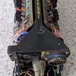
Which brings me on to this item. What this appears to be is a bearing indicator going by the description on the back. This is the display for the Radar Warning Receiver system which shows which direction incoming missiles are coming from so the pilot can release countermeasures and avoid being hit. Many thanks to the curator of BAE Systems’ Rochester Avionics Archive for help in identifying this item. BAE didn’t make the display as the radar division of Marconi who made this wasn’t absorbed into BAE systems. It is a green screen CRT with no video processing circuitry inside the box at all so no composite video input. All the circuit boards consist of is an X deflection board, a Y deflection board both of which appear to be identical and a beam control PCB. The EHT and other high voltage is produced by a module in the top part of the chassis.
I think I managed to figure out the 28V DC supply rail but it was taking more than the 5 amps my bench power supply could handle which going by the thin wires to the connector seemed way too much. There are numerous other connections too which I guess are for remote brightness and contrast control and there are 4 wires going to each deflection board other than the signal input. I’m not sure what these do or what they are for.
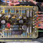
In short, there’s no way you would be able to make this display anything without any information or a bespoke system to drive it from. It is likely a vector scan display like an oscilloscope in x-y mode so it won’t be a conventional raster scan with a 15.625Khz line frequency for example. I can only guess what the 4 wires are for and there’s no clue from the components on the pcb’s. So for now it serves as a man cave item to display on a shelf awaiting the time when it is worth a lot more money than what I paid for it. Which could be a very long time.
Update:
I did try and power this thing up but figured that it needs several voltages to make it work. 26V AC is required along with two DC supplies which I assumed (incorrectly) was 28V DC as when applying power nothing seemed to happen then it caused my bench PSU to go overcurrent.
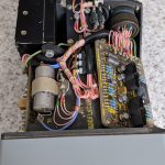
Upon inspection one of the four large power transistors at the rear had gone short circuit all round. I figured this must be acting as part of a voltage regulator circuit but the DC supply pins on the high voltage module were connected to a pin on the main input connector.
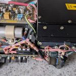
So obviously this didn’t appear to like 28V connected directly to those pins or the components have just failed. I also tried to remove the CRT to see if it was similar to an oscilloscope CRT but the housing it is fitted into is filled with liquid rubber cement / silicone sealer type material so removal is impossible without wrecking the unit.
Maybe if the CRT is removed it could be used for something like a scope clock project however upon further inspection it does not use electrostatic deflection like a scope tube; it has magnetic scan coils like a standard TV tube. This was verified by measuring them with a meter as the CRT cannot be removed easily due to the whole thing being mounted in a chamber filled with rubber silicone sealer type material as mentioned above. I presume this is to absorb shock and vibration but it makes the CRT inaccessible aside from the pins on it’s base.
But for now… I’ve bust it 🙁
I think seem as it is no use to me I might donate it to the Yorkshire Air Museum as their Tornado exhibit has this part missing from the instrument panel. It’s never going to be powered on so it may as well go to a good cause.
Useful link showing this display in the cockpit https://www.aircrewinterview.tv/tornado-f3-cockpit-with-rick-peacockedwards
Here’s some photos of the inside:-

