My Trust UPS battery failed on me last year and I was meaning to replace it but the cost of a replacement battery is almost equal to the cost of a cheap brand new UPS from dubious brands. I’ve always used APC SMART ups’s as they are very reliable and never seem to go wrong but man they are expensive.
APC do some cheaper models in plastic casing but they are no better than the cheap Trust / Belkin / Mustek types that often advertise with a massive VA rating but are yet much smaller than their APC equivalents. They often only have a 7 to 9Ah battery in them even in 2200VA models. I doubt they would last long at full load and I don’t just mean the battery. They only have 4 MOSFETS at the most which will likely explode the moment it switches to battery at full load.
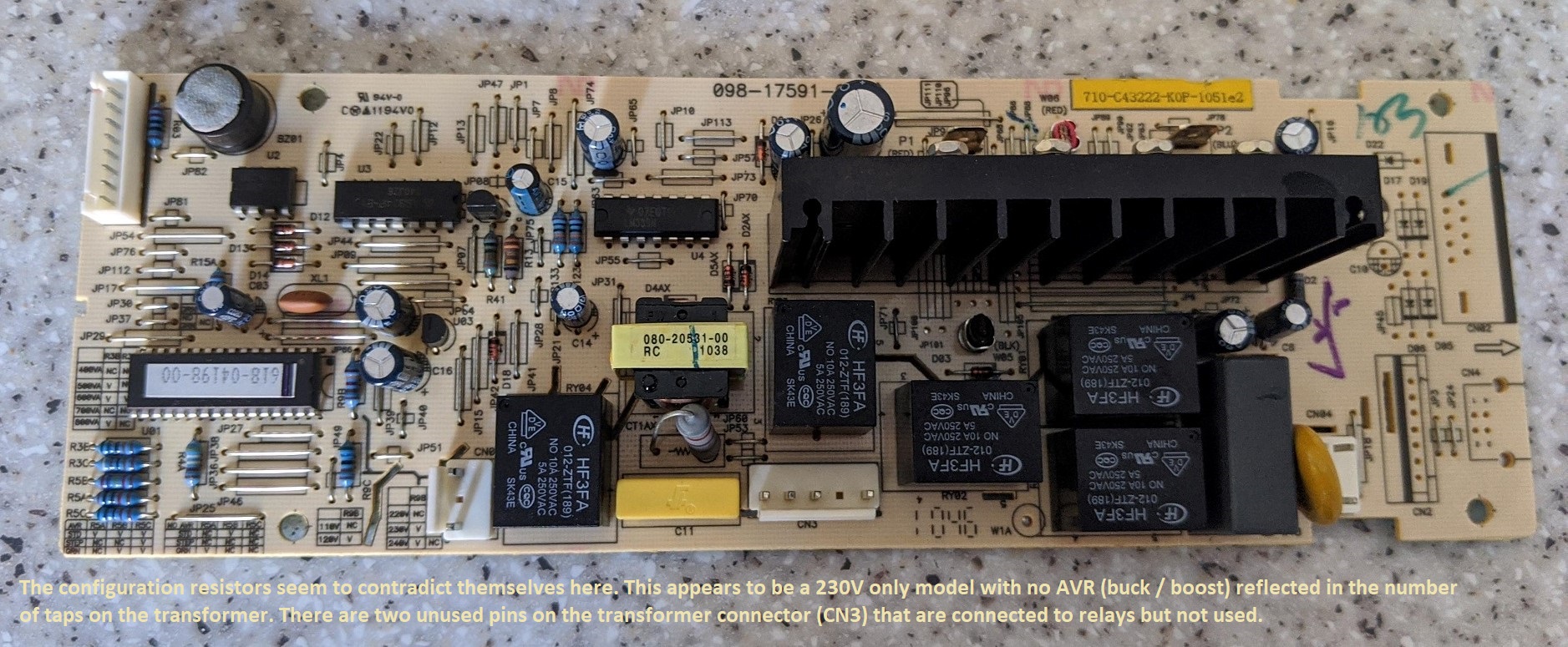
Anyway enough intro. I decided my UPS was just crap and not worth repairing; it was rated at 800VA and had a single 12V 7.2Ah battery in it with an advertised full load runtime of 5 mins. I pulled out the mainboard and noticed that it obviously uses the same board for different models with the configuration set by resistors. They seem to contradict themselves but from what I gather my UPS is set for 230V fixed with no AVR (buck / boost) and 600VA rating. No wonder it had a shit fit when I tried to put more than 600VA load onto it. Definitely said 800VA on the front and the box. Going by the transformer it is a offline / standby type although the board supports some kind of auto voltage regulation though it isn’t line interactive. There are two pins on the transformer connector connected to relays and other electronics but are not used. Perhaps by changing the transformer and configuration resistors you can make it a 220V model or one with AVR that switches taps on the transformer to maintain a stable output voltage without switching to battery.
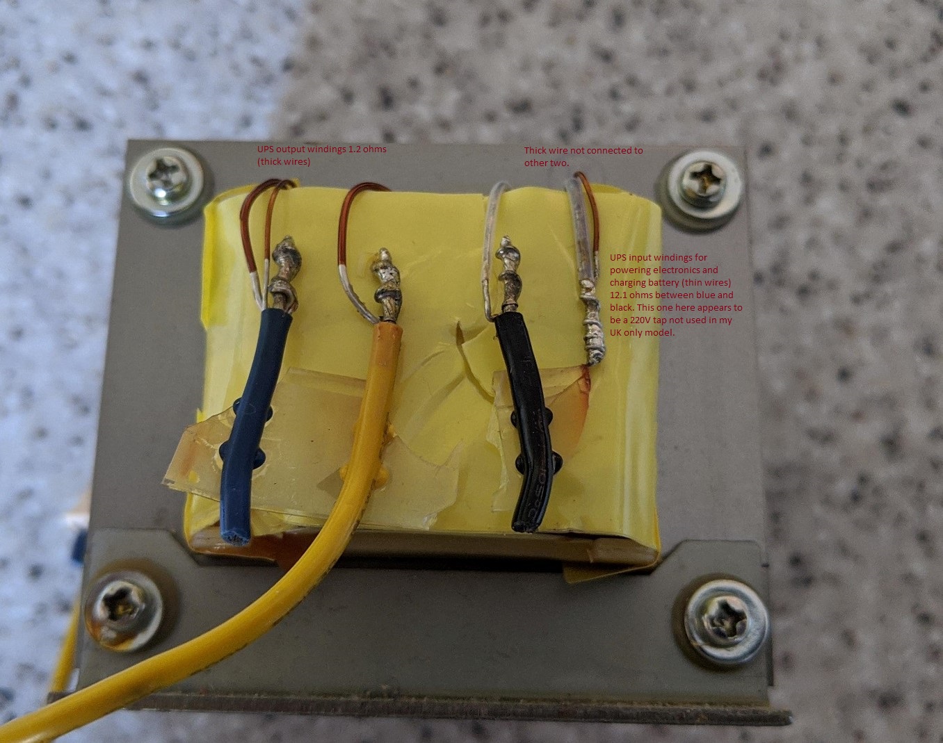
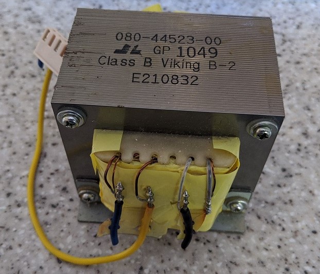
I do have a spare transformer from another UPS of the same type I previously scrapped and as you can see it has been pre experimented upon. That UPS had an electronics fault where it would go into overload alarm as soon as a light load was attached. I pulled off the yellow tape which revealed a fourth connection that wasn’t soldered to anything. There are two windings; one with thick wires that measure about 1.2 ohms and a tapped winding with thin wires. The connection at the far left is a common neutral followed by the UPS output winding when inverting then the live connection for the input winding used for powering the electronics and charging the battery. Finally the connection at the far right appears to be a 220V tap for the input winding. It has a thick wire also attached but has no connection to the other three connections. Very odd, must be broken internally but then why would it be connected? A fault maybe but both transformers were the same.
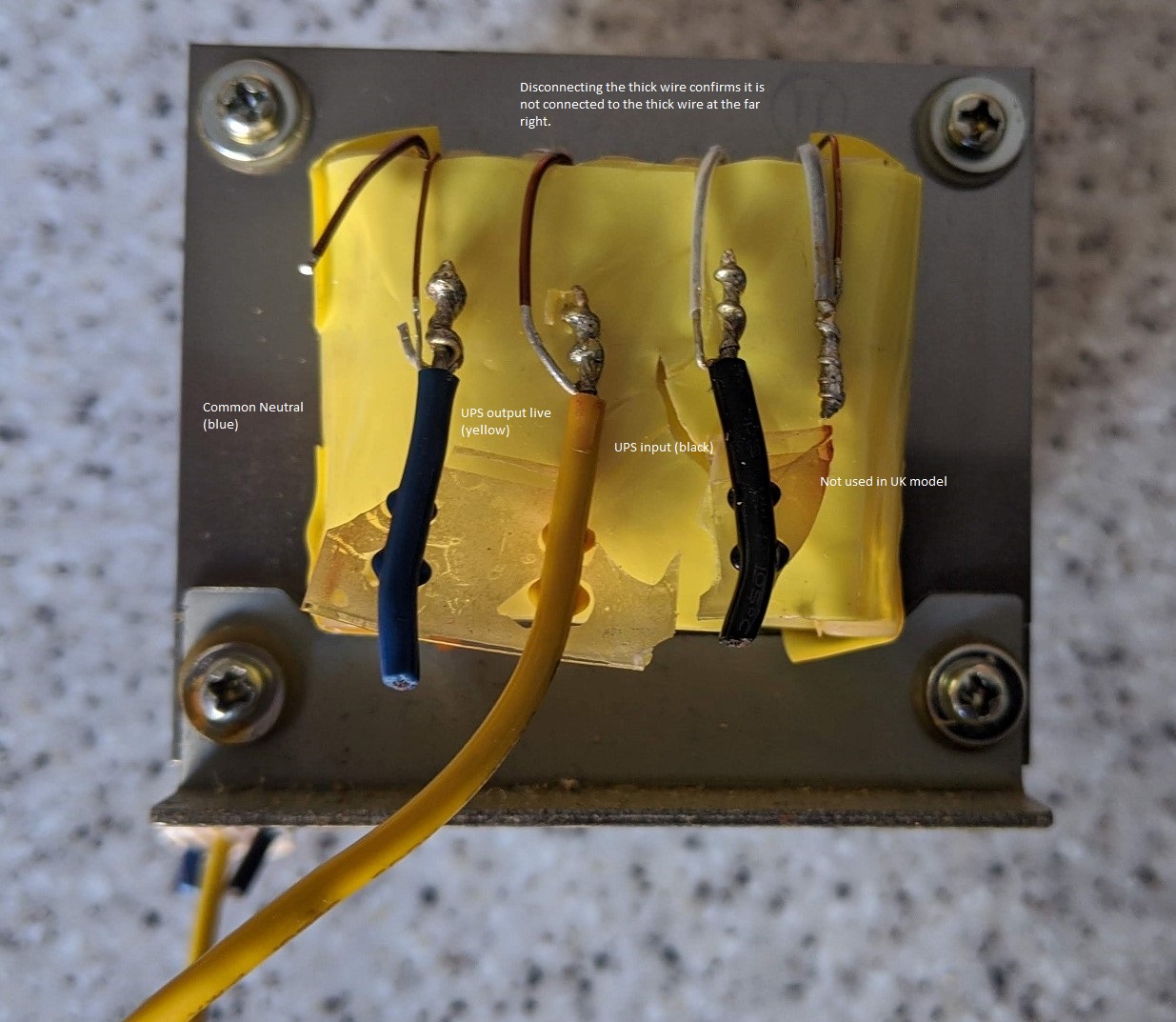
I cut the thick winding from the common neutral to confirm it was only connected to the connection with the yellow wire. So, to be able to use this transformer as a bench PSU I would need to connect the thin wires connected to the blue and black wires. These measured about 12.1 ohms and between black and the far right 0.1 ohms. Upon connecting to the mains the transformer only produced about 8.4V AC on the secondary (or primary depending how you look at it) I was expecting at least 12V and even connecting up the other tap only resulted in an extra 0.2V. I rectified the output and got about 10.6V DC which dropped back to about 8.6V when loaded with a 50ohm resistor which will put about 250mA load onto it.
So how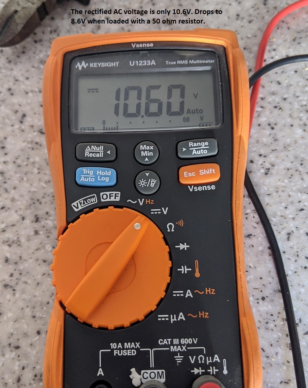 does this thing charge the battery with only 8 volts? Magic? Some sort of voltage boosting? I have no idea. With not having a schematic and finding it hard to trace where everything goes via the various relays I can only assume it uses the power mosfets to boost the voltage to around 14V needed to charge the battery. If anyone does know how this works please enlighten me…
So this transformer is pretty much useless. Even with one of those cheap Chinese boost modules you can get from Bangood the input voltage would be too low. You would not be able to draw any decent amount of current from the thing as as the output voltage from the boost converter increases so does the current drawn from the transformer. You can safely say, assuming 100% efficiency if you draw 24V at 2A from the boost converter the input current will be 4A at 12V.
I had a look around on youtube to see if anyone has done something similar. Which I found that quite a few have but they came to more or less the same conclusion as I did in which it’s not worth f**king about with. If you can find a UPS that has a 24V battery system you might get lucky. But they tend to be line interactive types that use an auto transformer which isn’t really safe to use reliably as a bench PSU. But again I don’t know why the manufacturer of this UPS uses a 12V battery but has a transformer with an output voltage of only 8V. I guess it’s to do with the ratio of the windings as a fully charged battery may put 12.8V into the transformer when inverting and this would result in the output AC voltage being too high. When used in ‘reverse’ a voltage boosting circuit must be employed. There again they could just alter the input windings. Who knows? But there’s sure as hell no way of finding out without a lot of reverse engineering which I can’t be arsed to do.
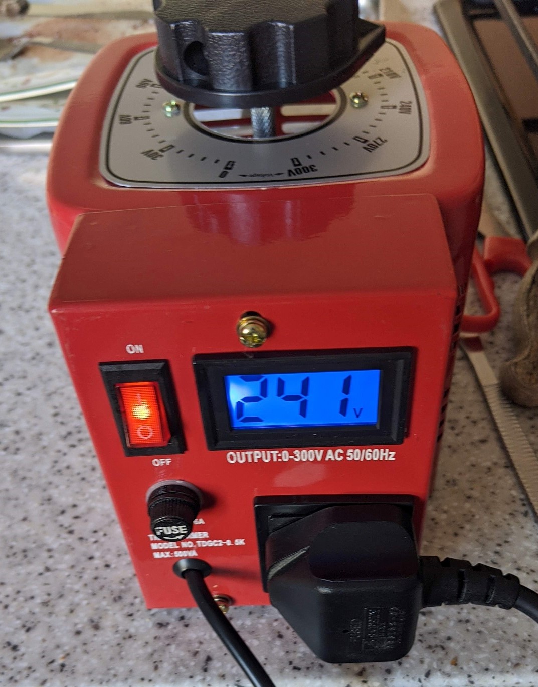
Finally experimenting with unknown transformers is dangerous and if you do not know what you are doing you could end up producing lethal voltages. Getting the primaries and secondaries the wrong way round could result in a few thousand volts being developed which will burn you / blow up your meter or blow you up. I would highly recommend you get a variac such as this thing below and gradually increase the voltage to the transformer carefully monitoring the output.
Anyway I wasted enough of my time on this thing and will send it for scrap. I even tried using it to blow some speakers and some small electronics components. There’s just not enough current available on the output to be able to do anything useful with. The most it could destroy was an LED. Even some 3 ohm speakers connected to it with an input voltage of 300V didn’t do anything.
Update on this article; I tried drawing more current from the transformer but the most I could get out of it was about an amp. Tried using it to blow some 15 watt 3 ohm speakers and it could not even manage that.
Here’s the answer how the thing charges the battery:
http://www.youtube.com/watch?v=Fj7e3WGUKO8
Hello how do you disable green mode on this exact model. It is freakin annoying when the ups turns off in 4.5 minutes because i dont have a >10% load
I didn’t know it even had a green mode. Looking at the manual it doesn’t appear to be possible. Someone did manage to modify the PCB by removing a resistor on a similar model but don’t know how to do it on this specific unit.