Re-using a microcontroller from a LCDmodkit USB204B.V02 board

On one of my very old computers I had one of those LCDmodkit PC status screens that consisted of a 20×4 LCD housed in a 5.25″ bay and was interfaced to an internal USB header on the motherboard via a USB2LCD controller. As there are no Microsoft certified drivers available for this device it was no longer used in my newer Windows 10 or later machines. I removed the USB204B board off the back of the LCD and used the LCD for another project. That left me with a controller which was pretty much useless. On inspection I found it had an ATmega8 microcontroller and a bit of digging I found that this is based off the LCD2USB project by Harbaum (link to original project here) and it appears that the LCDmodkit controller is basically a redesigned original using SMT instead of surface mounted parts.

LCD204B controller mounted on perfboard

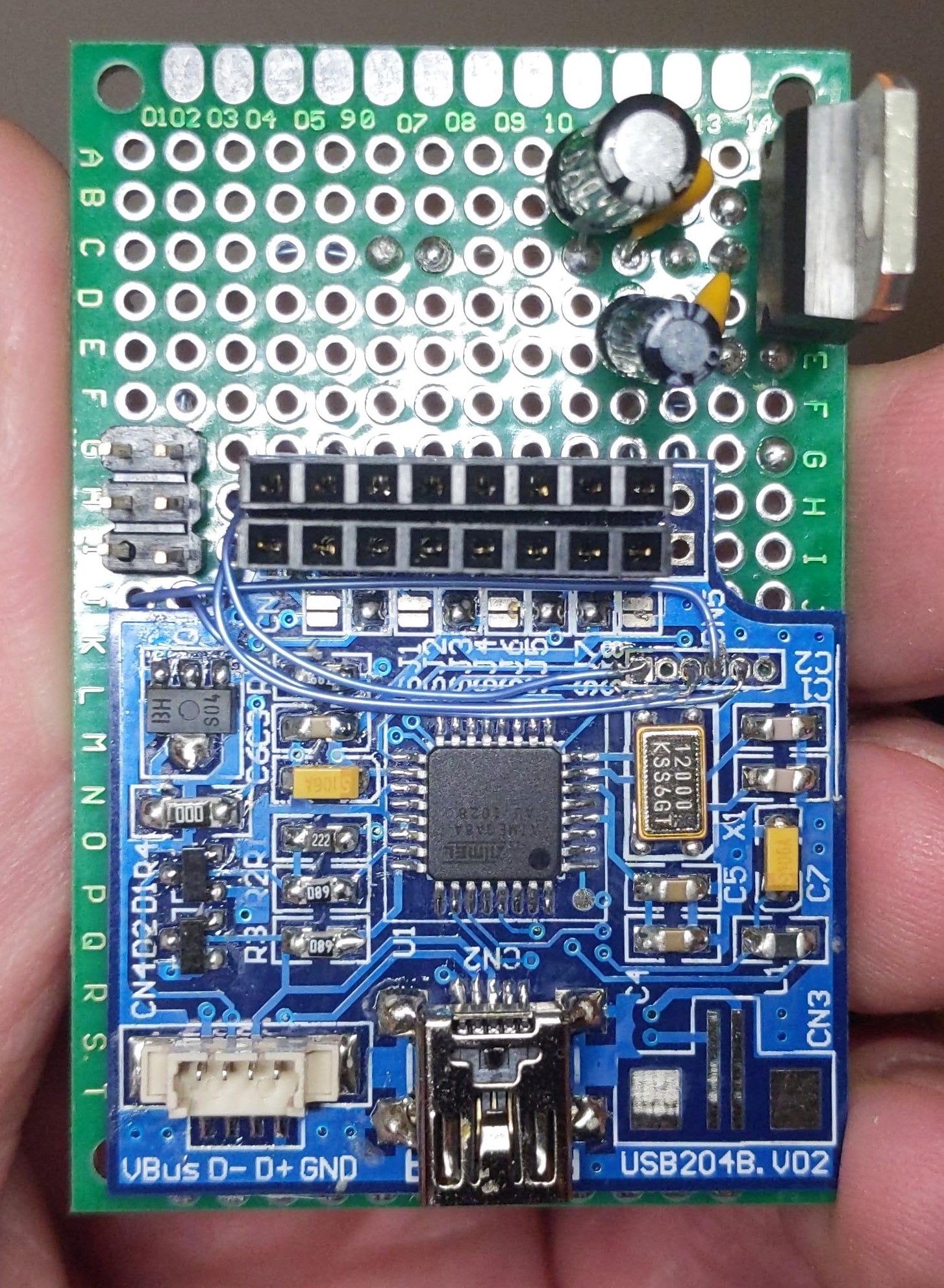
So I thought it is highly likely that the board could be reprogrammed and wasn’t locked. So I added a couple of headers to the former LCD connector and found, as in the schematic found on Harbaum’s project several of the I/O ports are broken out onto this connector. The rest are used for V-USB and serial and there is also a group of six solder pads labelled CN5 to the upper right of the microcontroller. I suspected this was for programming and poking around revealed this to be the case. The MOSI, SS and MISO pins were on these solder pads so I connected it to an arduino working as an ISP and uploaded a couple of basic sketches. Worked a treat but one thing to watch out for is the onboard crystal is 12Mhz not 16Mhz so anything that uses timers won’t work properly. However it’s great for very basic applications that involve sensors and activating outputs.

I’ve mapped out the six solder pads with pin one being to the right hand side of the photo. In other words pin one is nearest the edge of the board and pin six is nearest the microcontroller. I connected these via mod wire to a standard 6 pin ISP header on the perfboard.

Pins are 1= ADC6, 2= Reset, 3= MOSI, 4= SCK / SS, 5 = AVCC, 6 = MISO. 5V and power were taken from the 16 pin LCD header. The rest are easily found out by measuring continuity between each of the 16 pins and the pins on the microcontroller using a pinout as a reference. I used a 7805 regulator to power it but even if reprogrammed the original USB connector could be used to power the board.

Continue reading →

Nimrod MRA4 cockpit LCD display unit teardown (Thales LCD66N)

Whilst I was on covid lockdown I bought several avionics parts with the intention of making teardown videos and seeing if I could possibly power them up. If you are a frequent visitor to this site and / or my YouTube channel then you will already know this but for new visitors please check my other posts and my YouTube channel for more avionics teardowns.

I have a cockpit LCD display unit from an RAF Nimrod MRA4 which was a cancelled project to upgrade the existing MR2 aircraft which included new avionics and several aircraft were built but later scrapped before they entered service due to the project’s cancellation. Somehow many of the parts ended up on eBay and I’ve found by doing a little research these display units have found their way to home cockpit flight sim enthusiasts wanting to see if they can be used. Short answer to that question is possibly but from my teardown its likely they need a specialised video format and / or additional signalling to select inputs. My unit seems to be possibly faulty / broken as well but I will find that out once I get a power supply that can handle it as it draws over 5 amps at 28V. It’s explained in the YouTube video but for now here are some photos of the main boards.

Continue reading →

Teardown of a high end outdoor mast head Wi-Fi access point

Here I have a couple of defective enterprise grade access points that were decommissioned as they were suspected as faulty and were out of warranty. They are manufactured by Xirrus and are meant for outdoor high capacity Wi-Fi for public locations e.g. Stadiums, festivals etc. I thought I’d pull one apart and see what was inside before they were sent for scrap so I will share some photos here and give brief descriptions on what each major chip is and what it does.

I did a video below of the teardown but there is no narration. It’s good enough to get the point across but after all this is just an access point but a very expensive, enterprise grade one costing several hundred dollars.


Is it worth buying faulty tablets off eBay to repair & resell for profit?

I bought two lots of faulty laptops and tablets from eBay with the intention of repairing and reselling them as mentioned in my previous blog posts. Without repeating myself this was largely a success more so with the laptops and not so much with the tablets. The problem with the tablets not being profitable is because they are old and go out of date more quickly than laptops and the newer ones are more difficult to repair as they are usually glued together and cannot be taken apart easily. So, with this in mind I bought older models and avoided ones with obvious cracked screens. The majority of the faults were broken USB sockets which were replaceable but given the cost of the parts and eBay fees I only just broke even.

The other thing I found was some of these tablets had obviously come from computer repair shops and had missing parts and / or multiple faults as they had been used to make a good tablet out of several faulty ones and almost all parts in the ones I bought were faulty. Some were made to look like they had never been opened. Take this one for example; a Samsung  nexus 10 tablet which had a broken power / USB socket and a broken power button. I replaced the USB connector and power button but it still would not power up although the battery was charging. I removed the metal shield covering the CPU and flash chips and found that the flash chip had holes drilled into it. Now the seller had made a really good job of reassembling this tablet and making it look like it had never been opened. I was clearly ripped off here. Some of the others were in a similar state.

I thought I’d mention this for anyone who is thinking of buying faulty tablets to try and repair them. Watch out as most are junk unless you are buying from genuine private sellers selling three of them at most. Also they are often account locked and even if you fix them they are useless without being de-registered by the previous owner. This is why I avoid apple products but the latest Android devices are doing the same thing too.

So, take my advice. Don’t bother buying bulk faulty tablets and phones unless you like wasting your money.

More headaches – an Asus X205T that won’t boot from USB

I bought several laptops and netbooks off eBay with a view to refurbish and sell them; I got around 7 laptops and 9 tablets and netbooks for just £100. One of the netbooks was an Asus X205T that had it’s eMMC drive encrypted with bitlocker amongst other issues such as a dead battery and faulty keyboard. The netbook would only boot into the bitlocker recovery screen and would not allow booting from USB as it just returned to the bitlocker screen. To get around this problem and seem as I wanted to remove the existing data anyway I selected skip this drive on the bitlocker recovery which took me to the standard windows 10 repair recovery menu. Resetting the to factory settings was out as the storage drive was locked. So to get around this problem I went into the command prompt and removed all partitions with the DISKPART utility.

However upon rebooting the netbook just went straight into the BIOS and would not allow any boot options to be changed. It was set to USB for Windows to Go but would not boot anything. To cut a very long story short in order to get Windows 10 to install you must use a old USB2 stick (not USB3) and use the 32 bit version of windows. Only installation media created with the official Microsoft tool would work. Plugging this in and rebooting made it boot to the windows installer.

The reason for all this palaver is because the UEFI firmware is only 32 bit and will not see 64 bit code. Neither will it see USB3 pendrives, USB sticks etc. So if anyone ever has this problem now you know. This could apply to any older netbook and tablet running Windows 8.1 or later with a UEFI BIOS. See my previous post for a similar issue with a Dell Venue 8 Pro tablet.

Clean install of Windows 10 onto a Dell Venue 8 Pro tablet – major headache!

I had the unfortunate thing happen to my dell tablet computer – a windows “feature update” totally bricked it with a BSOD during install resulting in the tablet stuck on a screen saying windows encountered an unknown problem during installation or something like that. The only thing I could do was click OK which rebooted the tablet resulting in the same screen.

To cut a long story short this tablet originally came with Windows 8.1 and was upgraded to Windows 10 some time back. Now later builds of Windows 10 are not compatible with the Venue 8 pro unless you update the BIOS first. Too bad the windows installer didn’t detect this and went and installed the latest build anyway resulting in a bricked device. The original dell recovery partition was also overwritten when it was upgraded from Windows 8.1 to 10.

Now as this device only has one USB port which is also used for charging I had to fully charge the device and grab an OTG cable, a USB hub, a keyboard, a mouse plus a USB stick. To get windows to install I had to go into the BIOS by holding down volume down as the tablet starts up then releasing and changing the boot order to boot from USB. Now I had to download an older .iso using rufus which would work on this tablet then image it to a USB thumb drive. However once the setup started I was presented with a screen saying that an additional driver is required and the installer would not see the files on the USB stick despite booting from it. All I could see was the internal eMMC storage.

Continue reading →

Aircraft avionics teardown – Honeywell symbol generator

I obtained another interesting piece of aircraft avionics – this time a symbol generator computer that is used for generating the graphics and video signals for the CRT displays in the cockpit. From what I can gather there is typically 2-3 of these units in the aircraft with each symbol generator driving two displays so there would be one for each side of the cockpit + one backup.

It dates from around 1990 so it’s approximately 30 years old at the time of this article. The electronics inside are very space age with radiation hardened gold topped IC’s.

Video card (rear PCB)

It consists of various cards which are 2 x video driver boards, the CPU board, WXR scan converter board and several I/O boards. The computing technology isn’t anything to write home about but it would have been state of the art at the time. There is an Intel 80c86 used as the main CPU with some Zilog Z180 compatibles on the video cards.

Here’s a photo gallery with descriptions of the boards and a YouTube video

Continue reading →

NTP clock only version of my ESP8266 based display

As there was interest I have released firmware for my YouTube statistics and clock internet connected display featured in my previous post for users who just want an NTP clock and don’t require the YouTube counter functions. This clock automatically gets the time from the NTP server and synchronises it with the software based RTC running on the module every hour. A button toggles daylight saving time on and off.

The source code and pre-compiled .bin file can be downloaded in the links below. Use ESP8266flasher.exe tool to upload the firmware which is available on Github. I can’t post the file here but if you click on the link or google search for the tool it will show up. ESP flash tool settings set as follows:-

Baud rate 115200, flash size = 4Mb, DIO mode, 40Mhz (not to be confused with CPU clock speed) and finally flash to location 0x00000 as shown in the pictures below. Finally set the COM port on the operation tab and click the program / flash button.


Links to firmware

Internet clock (UTC / GMT timezone)

Internet clock (CET timezone)

Please contact me for other timezones.

Setup instructions and manual

Source code

Version 1.2 of the firmware and source code. In this version I added a DST mode on / off indicator on the rightmost decimal point of the display. The download link is for the UTC / GMT timezone. Contact me for other timezones.

Licence: creative commons attribution-non commercial (CC BY-NC)

ESP8266 based NTP clock with YouTube statistics display

I made some internet connected 8 digit 7 segment LED displays using a NodeMCU and Harris semiconductor ICM7228A LED driver ICs the latter of which were salvaged from old aircraft avionics. As the chips would unlikely sell on eBay I decided to make them into a project and improve upon my earlier YouTube counter project which displayed the subscriber and view counts on a 4 digit and 8 digit LED display.

This version uses a 8 digit 0.56″ LED display and shows the current time by default which is obtained and set automatically by querying the NTP servers available on the internet. A button on the rear selects the mode to display; clock, number of YouTube subscribers to your channel and total number of video views. The button also toggles DST on and off by pressing and holding the button for more than 5 seconds and releasing it.

I fitted the completed PCB into a photo frame to complete the project and able to display it in my home. I have made full instructions available to download if you wanted to make one yourself and I also have a limited number for sale (now sold out!) on eBay which you can purchase by going to the links down below. Please note that you will need to obtain a YouTube API key for the YouTube statistics functions to work. This is free of charge but requires a little work on the Google developers page.

To sum up this unit is an universal 8 digit internet connected display which could be used for a number of things but in this example it is loaded with firmware to display the time from the NTP time service and also provide YouTube statistics of your channel showing subscriber count and total video view count. Due to YouTube’s limitations implemented in 2019 the counter will only show exact numbers of subscribers up to 999. After that it will begin rounding them down on a sliding scale starting with the lowest 10. For example 1234 subscribers will show as 1230 and 12345 subscribers will show as 12300 subscribers. Hence this product is suitable for small channels and producers who want to keep an eye on their subscribers as well as know the time!

The counter works by connecting to the internet through an ESP8266 WiFi module which has a 32 bit RISC-V CPU onboard running at 80Mhz with some spare flash space for user programs which can be programmed in C++ or Python. This is where the firmware for operation is stored. An ICM7228 display driver chip handles the multiplexing and display blanking and drives 8 common anode high efficiency displays directly without the need for current limiting resistors.

Instructions for use including obtaining API key

YouTube video

Source code

Schematic

PCB design files (KiCad)

Pre-compiled .bin files (upload using the NodeMCU firmware programmer; esp8266flasher.exe) flash size set to 4Mb, DIO mode @ 40Mhz (not to be confused with CPU clock speed) and flash to location 0x00000. Use 115200 baud.

UK and Europe

Please click on continue reading for the photo gallery.

Continue reading →

The DM134B 16 bit shift register with constant current LED drivers

I have quite a few DM134B IC’s which are 16 bit shift registers complete with constant current LED drivers built in so I decided to make something useful from them. The chips require minimal components; LED current is simply set via an external resistor which is far better than having to use 16 individual resistors. The snag with these chips is that they are surface mount in the SOP-24 package. So to fit them into a prototype board I bought a SOP-24 to DIP converter and soldered one to it and began to experiment with an Arduino and found that they work just fine with the shiftout and direct SPI functions. Just like any other latched shift register.

One chip behaves like two 74HC595’s in series albeit the output enable is active low instead of active high like the ‘595. I wrote a small demo program that counts from 0-999.9 seconds to test them and had some sample breakout PCB’s made in which an Arduino Nano could be fitted to. They worked well so they will definitely be useful for future projects. The demo board contains two DM134B’s daisy chained driving four 7 segment displays which can be used as a voltmeter, temperature readout or indeed any project that needs a 4 digit display. As mentioned above the demo board has space for an Arduino Nano and pins are broke out onto adjacent headers so that they can be used for another purpose such as analog inputs etc.

Here’s the schematic and photos of the demo board. I’ve kept one but the other four I’ve put on eBay as I’m sure they will be useful to someone. The firmware for the demo board can be downloaded here.

Link to Ebay UK where you can purchase these https://www.ebay.co.uk/itm/193904797643

Electronic tape measure using HC-SR04 ultrasonic sensor demo code

Also available on my Tindie store https://www.tindie.com/products/22759/

Instructions (PDF describing the operation and pinouts) DM134B PCB instructions

Video https://youtu.be/-rPsJusRiV0

Schematic:-


A photo of it working:-

Racal Avionics data entry device / CDU teardown and test

This will be the last teardown video for a while and this time I have a Racal Avionics CDU allegedly from an RAF Nimrod which I obtained some time ago and discovered that it communicates with a host system over standard RS422. Now, thinking I might be able to connect it to my PC or an Arduino or any other type of microcontroller I set about seeing how it worked. Armed with a RS422 / RS485 to USB adaptor and an oscilloscope I powered it up (just needs 28V DC) and probed around to see what I could find. The unit does indeed power up and displays a self test screen. Other than being able to control the screen brightness pressing any of the other buttons did not do anything. So I took it apart to see what was inside…


Model number is 80794/SS302 NATO stock number 5826-99-1603965. It dates from around 1990 and uses a couple of Motorola 680x series CPU’s. It appears to be a serial terminal device. There are no ARINC or MIL-1553 buses on this thing although a look at an EPROM dump suggests that is an option. I was unable to get any serial data out of it unfortunately on the RS422 port and even directly on the UART chip itself. I dumped the EPROMS on the boards which reveals that the device configuration is set via straps connected to the rear panel of the unit. However pin 1 was not indicated and what needs to be done with it e.g tie it to ground or +5V. I didn’t get very far with it but I noticed that the CRT is has a line scan rate of 15.625Khz which is the same as analogue European TV’s. Hmm.

Continue reading →

Using large / high current 7 segment LED displays with the MAX7219

I have some largish 7 segment displays which are 0.8″ in height but I found that they were dim when driven from a MAX7219 even at full brightness. I found that this was because the LED displays I were using need around 15 mA for a decent amount of brightness, 25mA ideal. However the MAX7219 only has a maximum peak current of 40mA per segment; now that is peak current so that means with a multiplexed display that will be divided by the number of digits to give an average current of 5mA, or if you prefer the equivalent DC current. Now as my displays need 15mA that simply isn’t enough hence the dim display.

So to get around that problem I used a UDN2982 as a source driver between the segment outputs and the LED segment anodes. 47 ohm current limiting resistors were used (more on that later) and a ULN2803A was used as the sink driver on the digit outputs. Now as the digit outputs will be at a logic low level I had to use an 74HCT04 inverter between the MAX7219 and the ULN2803A as the ‘2803A needs a logic 1 to ‘turn on’ it’s outputs.

I used an LED supply voltage of 7V as 5V wasn’t enough to get a decent amount of current through the displays as the UDN2982 drops about 1.6V across it and the ULN2803A about 1 volt. Together with the voltage drop across the LED display I was only left with 0.4V to play with at a supply voltage of 5V. Both the ‘2803A and the ‘2982 have a absolute maximum current of 500mA for the entire chip so I aimed for 60mA peak current per segment which gives an maximum current through the UDN2982 of 480mA when the worst case scenario of the displays showing 8 and the decimal point is lit. 60mA divided by 8 digits still only gives 7.5mA average segment current – still not enough but as I was using only 4 digits I set the MAX7219 scan limit to only 4 displays which doubled it to 15mA equivalent DC current. This resulted in an acceptable display without overloading the driver IC’s. I did try it on 5V with 6.8 ohm resistors giving around 7mA current but it didn’t work.

Continue reading →