A list of serious Arduino based projects I have made that I think are worth making by others if you so wish. I have not included any experimental or prototype projects; if you want to see everything I’ve dabbled with and talked about please see the home page.
A large 6 digit clock made from scavenged 1.8″ + 0.8″ LED modules
I bought some scrap electronic parts from a car boot sale (flea market) and in the lot were some PCB’s with large (1.8″ and 2.3″) 7 segment displays which when tested lit up with a nice orange – red colour. They were originally from fruit machines and some call centre call waiting displays so I decided to do something with them. 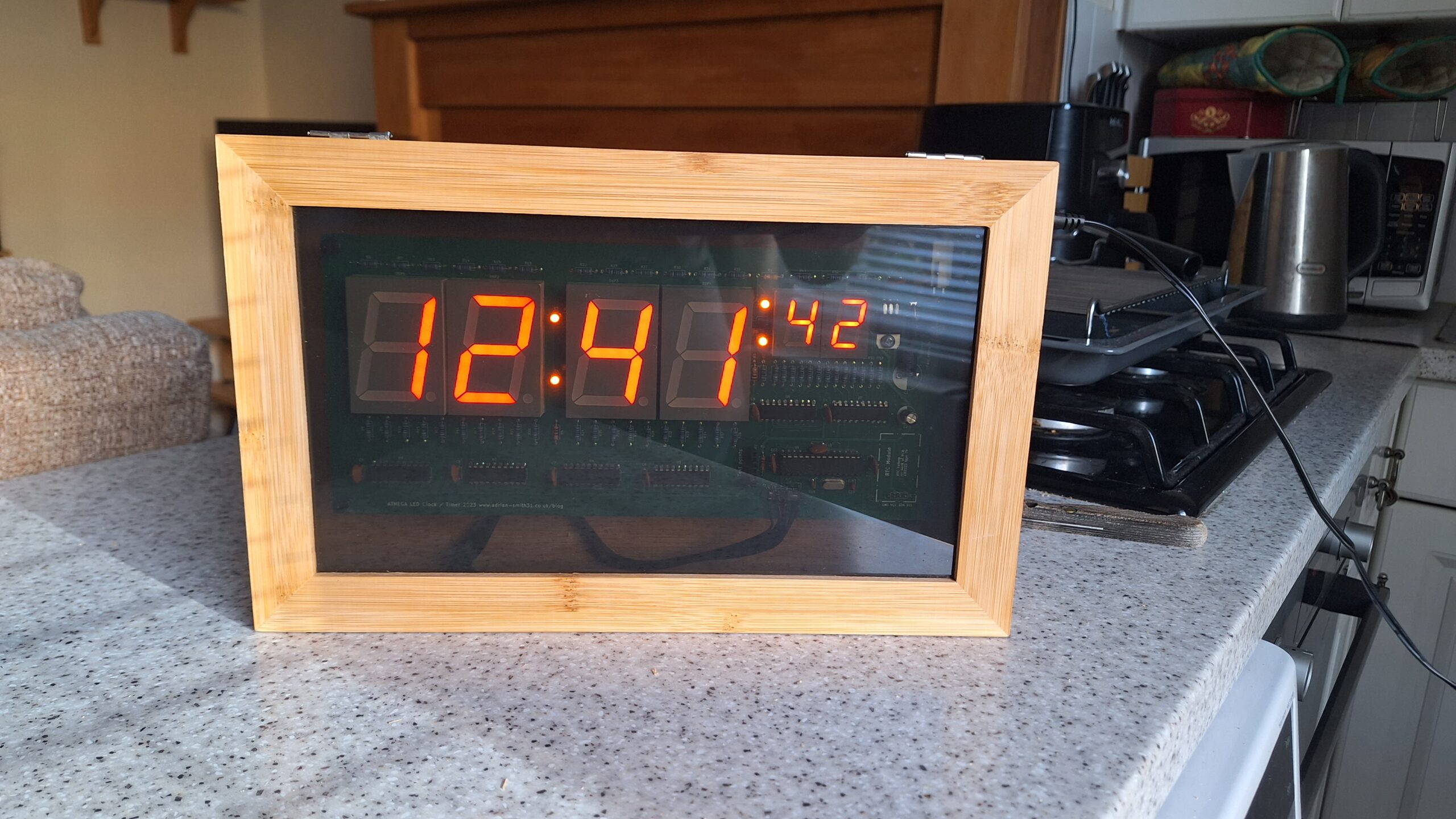 As I haven’t made any projects for a long time and needed to practice my programming and PCB design skills I made a large clock / timer which could be seen from a distance. I have made several clocks, one a bedside alarm clock which I still use nearly 5 years later and a couple for my living room. I made two styles using dot matrix modules and kept one, the other I took to work to use in the office.
This third design is more traditional and uses 1.8″ high digits for the hours and minutes and 0.8″ high for the seconds rather than dot matrix display modules. It’s a large PCB measuring 270 x 110mm and I had trouble finding a suitable case for it. In the end I settled on a tea bag case with a clear glass lid. It has no branding or logos on it which made it ideal for a case once the internal compartments were removed.
Not sure what I’m going to do with it yet but I made a couple – one I sold on eBay, the other might do for a garage / shed clock or something.
You can buy a blank PCB from my eBay store using the links on the right. Sorry sold out of completed clocks, just the bare PCB’s available.
An NTP clock using an ESP8266 programmed with Arduino IDE
In reference to the improved version of my YouTube statistics display (below) I decided to make a clock only version as I had made several of the improved YouTube  counters and sold them on eBay with an option of housing them in a black photo frame. I sold most of them but one customer said he didn’t want the YouTube stats (he hated everything Google) so I made a separate version of the firmware for him and then advertised the remaining counters as clocks only on eBay.
These were much more successful selling to customers worldwide and I even have a couple left. I call these my “universal internet connected display” and I’m keeping a couple myself for debugging and adding future improvements plus for the YouTube stats counter version if Google change the way their API works the code will need to be updated. I might write some more firmware in the future where numerical data needs to be displayed grabbed from an online source. They make ideal gifts for techy type family members or friends.
The hardware is the same and consists of an ESP8266E NodeMCU module, an ICM7228 (or ICM7218) display driver IC and 8 0.56″ LED modules. A pushbutton toggles daylight saving time on and off. As this gets its time from the NTP service it does not need an real time clock thus simplifying the design and reducing cost. It syncs with the NTP service at startup and on the hour thereafter. There is no alarm function unfortunately.
As you can see the display is red and the ICM7218/7228 requires high efficiency LED modules that are bright enough with 8mA of segment current otherwise the display will be dim with standard LED modules that have a typical operating current of 20mA. Alternative colours can be used as I tried green modules but the display was a little dimmer due to the difference in forward voltages and efficiency of the LED segments.
YouTube statistics counter on 7 segment displays 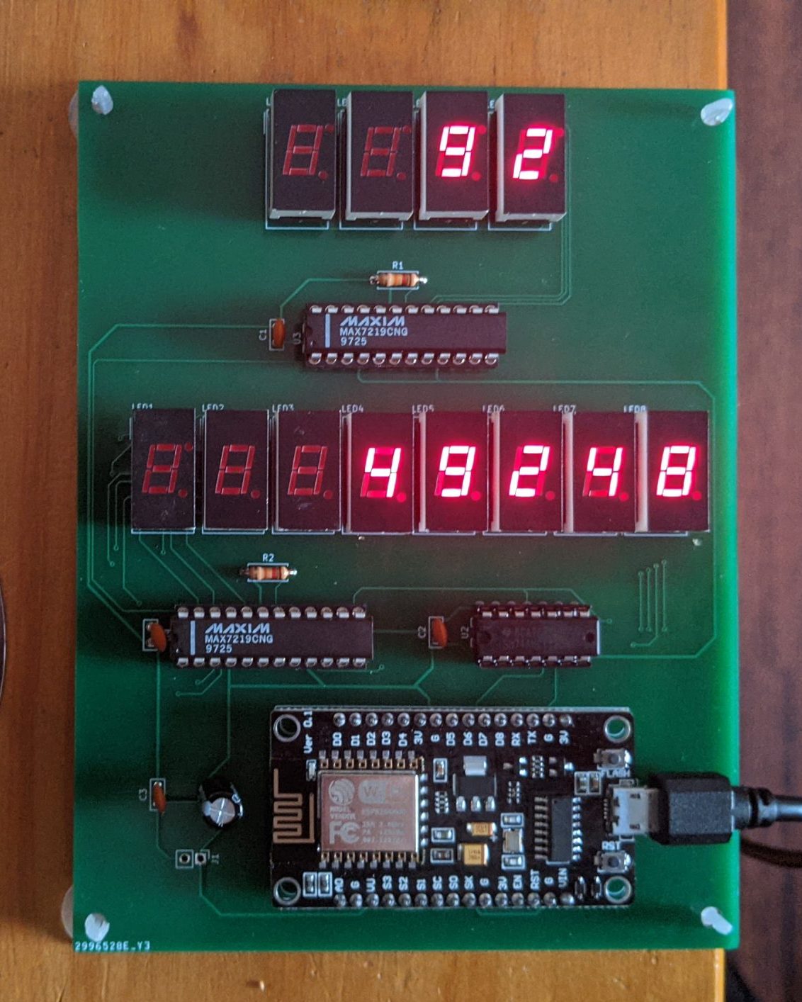
This is my second project using Arduino on an ESP8266 module which is a Wi-Fi module typically used to add wireless networking to microcontrollers. However the ESP8266 module has a 32 bit 80Mhz RISC CPU on board with plenty of spare flash space for your own programs. So for smaller projects the entire thing can run on the module itself. With a few I/O ports and Arduino boards manager support you can basically use this as an Arduino with built in Wi-Fi.
So as I have my own YouTube channel I decided to make a statistics display for it. This project displays subscriber counts on a 4 digit display and views on an 8 digit display. As my channel is small I thought it would suffice. The displays are 0.3″ common cathode LED modules and are driven from two MAX7219 display drivers which handle the multiplexing making code much simpler.
The other chip you see in the photo is a logic level translator which changes the 3.3V level signals to the 5V logic level the MAX7219 requires. I have used genuine chips here; some Chinese knockoffs will work just fine on 3.3V logic inputs. They also 100% need the decoupling capacitor across the power pins as close to the chip as possible. Something to watch out for when prototyping on a breadboard and omitting the capacitors which we often do. I
I later made an improved version that has a single 8 digit display 0.56″ height which includes an NTP clock function. This uses ICM7218 / ICM7228 display drivers. A choice I made due to a large number of common anode LED displays and ICM7228 chips I salvaged from scrap equipment so I put them to use rather than buying something else. A link to the project page is here.
Bench PSU with ATTiny 85 based electronic fuse

I decided to make a bench power supply for a younger relative so I decided to add some safety features to prevent it from being overloaded. As I had a few ATTiny85 chips around I decided to use the Arduino IDE to write some code for the ATTiny85 using the attiny board library by David A Mellis available within the Arduino IDE’s boards manager. This basically allows you to use other AVR processors that are not officially supported.
The ATtiny85 monitors the current via a sensor and will disconnect the output if it exceeds the pre determined limit set in the firmware. It also controls the output on / off via a pushbutton which it turn switches a relay on the output. See the project page for more details.
Dual colour version of animated clock
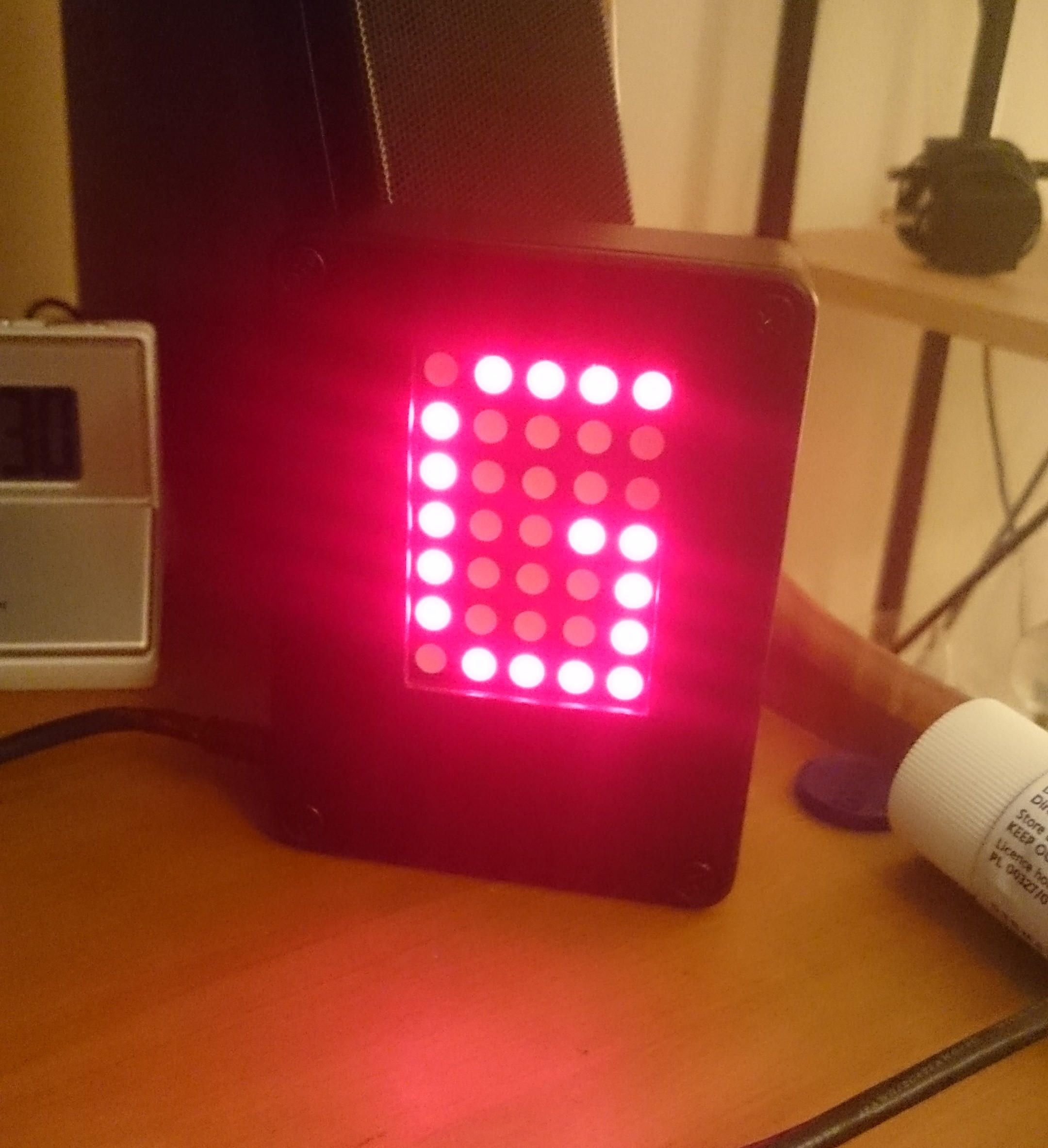
This is a different version of my earlier pong clock that uses a bi colour 16×32 LED matrix that is loosely based on the HUB75 standard. It uses Adafruit’s standard library and has some different modes to my older version. The modules are not perfect and can be hard to read but it was mainly made for something to do whilst we are all in quarantine.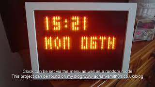
An arduino Mega 2560 pro clone was used as the controller and this is the most complex project I’ve put together so far. There were a lot of connections to the display and as I’d assembled it on perfboard instead of veroboard (required due to Mega2560 clone) there were a lot of connections to make on the back of the PCB.
The clock has power saving features where the main display can be turned off and time is displayed on a standard 7 segment display underneath the matrix. This can be at set times or turned on and off manually with a pushbutton.
NIMH AA and AAA battery tester
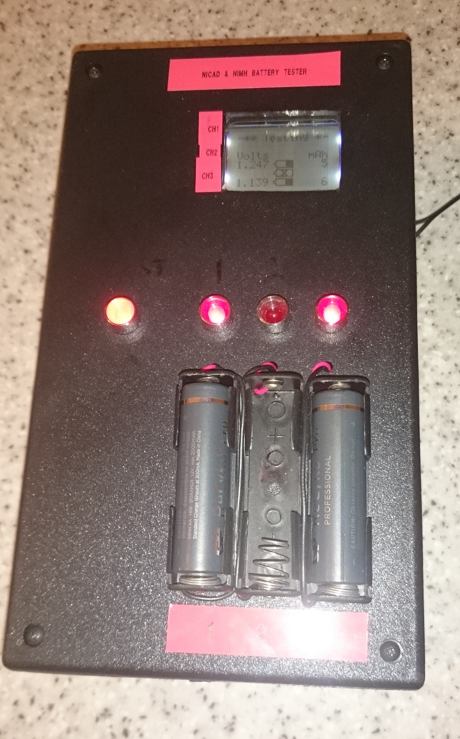 An automatic battery tester which discharges up to 3 AA or AAA cells and displays the resulting true mAh rating on an LCD. Can be adapted to test lithium cells with code modification. Originally based on a project by Brian Hobbs but has some modifications by me to improve ease of use and accuracy. Uses an Arduino nano (Mega 328) as the controller. Proved to be quite accurate as long as the 5V supply voltage is kept to as close to 5V as possible e.g use a good quality regulator.
LCD alarm clock with multiple alarms and 1 sec per month accuracy with DS1307 RTC.
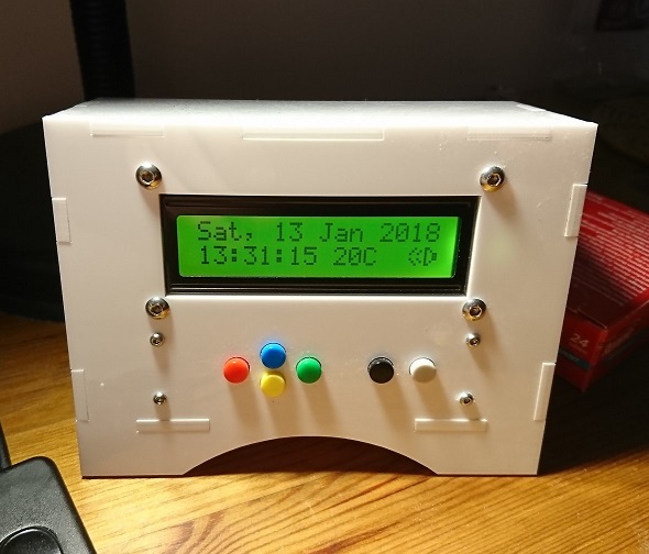
A decent alarm clock which displays time, date and temperature on a 16×2 LCD. Features multiple alarms with several melodies and up to 1 second per month accuracy with a standard DS1307 by using code to compensate for time drift. Again uses an Arduino nano but a Uno can be used with the case used in the project. Due to some of the changes I made to the code this should be used in 24 hour time display mode but a larger LCD could be used instead.
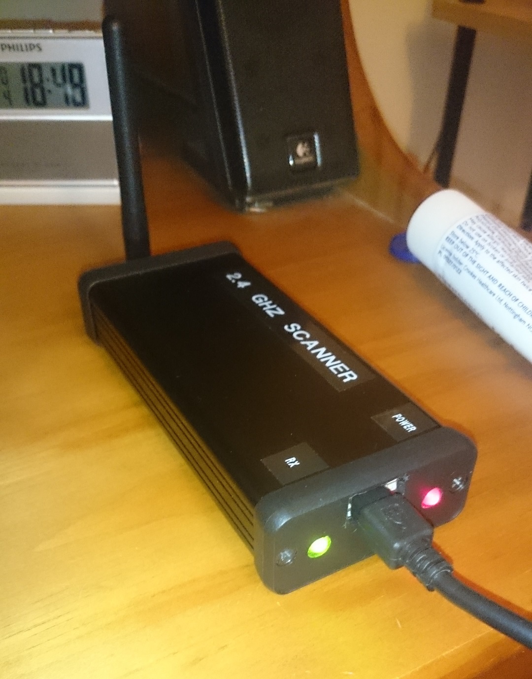
A simple wifi band scanner which was built to detect interference from other non wifi devices that use the 2.4Ghz band. Displays output on a serial port and uses the poor man’s wifi scanner base source code. Useful for diagnosing wifi signal problems. This came in handy for finding the cause of wireless signal dropouts when signal strength was OK and routers replaced to no avail. The problem was external interference which only this scanner can detect rather than your usual smartphone app.
Not really a serious project as such but this was completed and cased and would come in handy for a educational project or simply to display a custom message during special events. Two further revisions were made, the first added a clock function that would show the date and time before the message and the third did the same replacing the message if a sensor input threshold was met. This was used with a gas sensor for experimentation during the planning of a future project. It serves as a clock / scrolling message display now.
Gas & smoke detector / air quality meter
 This is another quick gadget I built as I have been experimenting with gas sensors for a planned project in the near future. This is an arduino based gas monitor which uses a MQ-2 sensor to detect hydrogen, methane, natural gas, alcohol and smoke. I had finished my experiments with the MQ-2 sensor and decided it was unsuitable for the planned project which was to detect unsafe levels of gas in battery charging rooms. I had a spare case and a Mega 328 microcontroller which had some faulty pins so I used it to build this simple device as I didn’t need all pins. I have removed the original version of this project as all it did was display the analog value on the 7 segment display. The new version of the code uses a formula from the datasheet to calibrate the sensor to give a more meaningful result. What this does is calculate the approximate PPM value of the gas the sensor is reading from the slope curve response from the device’s datasheet. It’s still not going to be accurate but much better than displaying just the raw analog value.
6 input digital voltmeter with up to 50V range
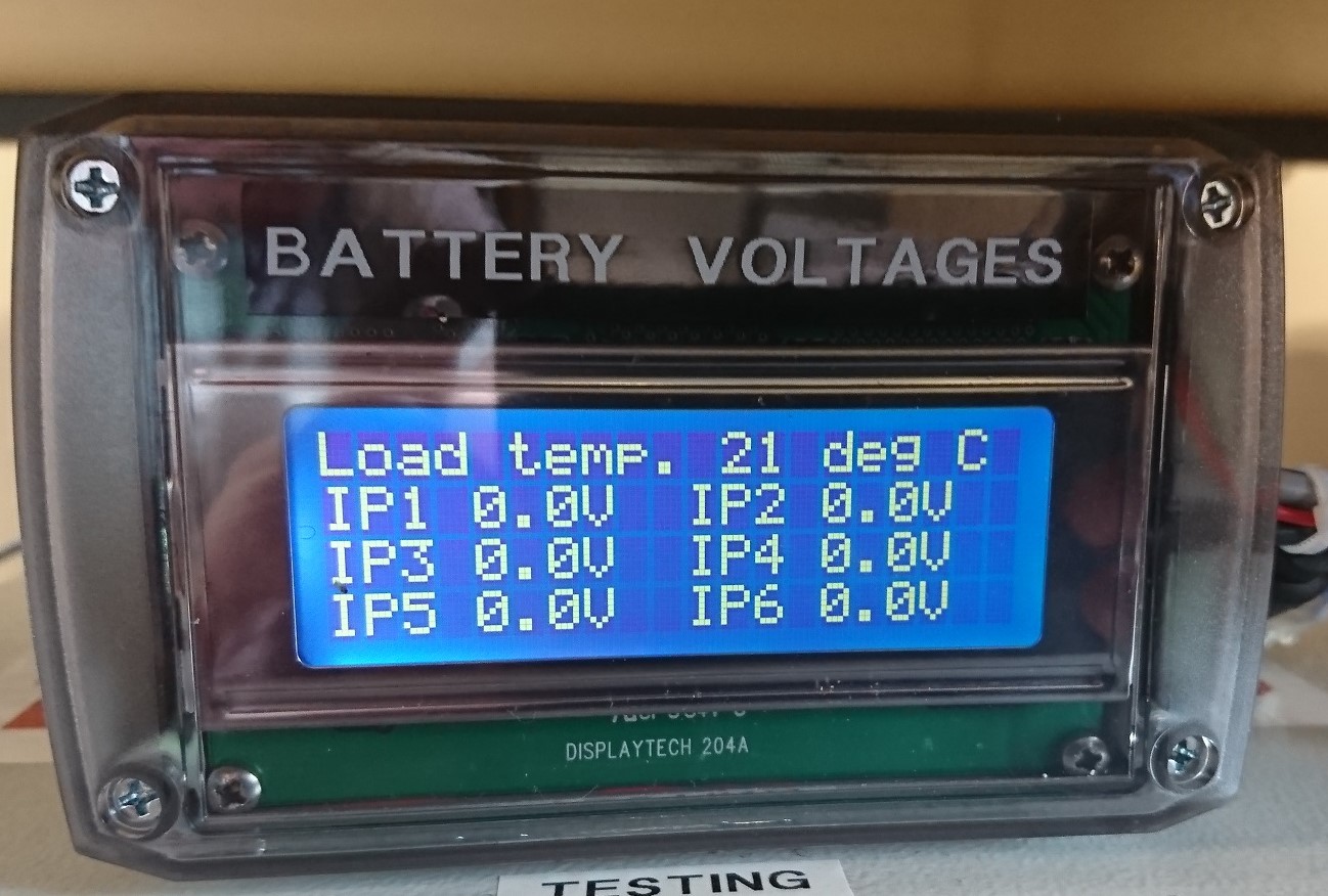 This was designed as an add-on for a battery tester we use at work but can be used for any situation where the need to measure up to 6 voltages at once. It is powered from a 24V DC supply and uses an Arduino nano as the microcontroller. The incoming 24V supply is dropped to 9V via a regulator so it can be fed into the nano board. It uses the default analog reference as accuracy wasn’t a must have in our application (its only accurate to one decimal place) but for other uses an external precision reference IC should be used. However the code has the ability to calibrate the input channels to a reasonable level.
H2S Gas detector & monitor with automatic charger disconnection
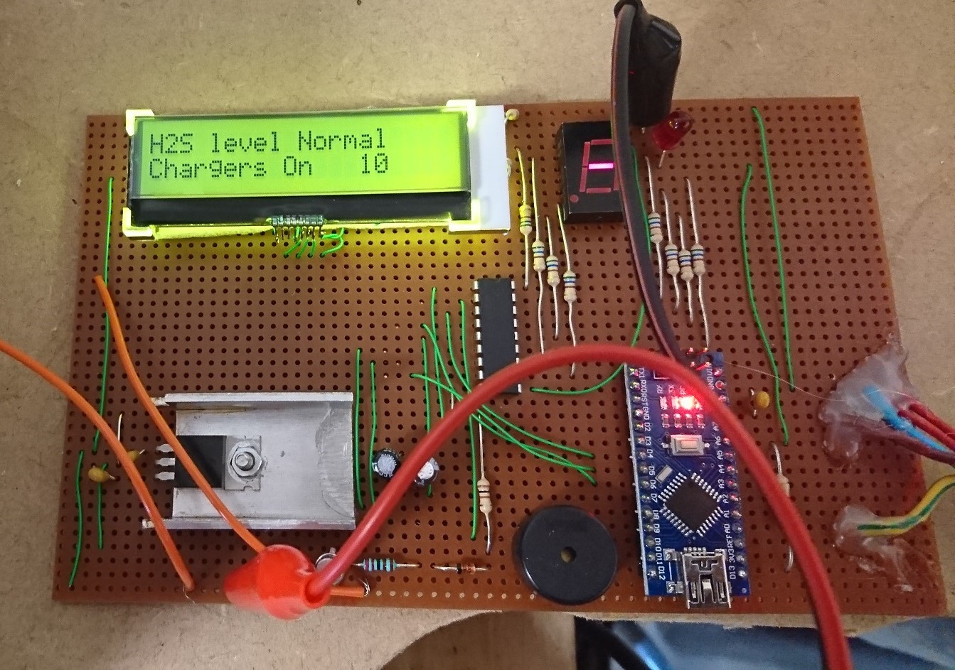 This is a project I made for work which monitors Hydrogen Sulphide levels in the area where we charge our lead acid batteries. Often batteries are left on charge unattended so I designed a system that would automatically turn off the power to the chargers if gas from a faulty battery was detected. With it simply turning on a relay to disconnect the power it could also turn on an extractor fan. The monitor will also sound an alarm and continue to do so even if gas levels return to normal. An LCD shows how long ago the alarm was tripped. The system can then be reset after the faulty battery identified and the power is restored.
Animated LED matrix clock with Pong and other modes
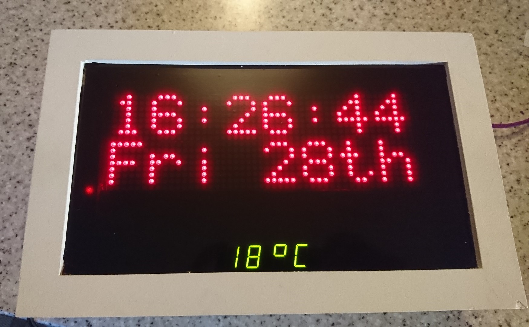 An animated clock showing the time and date on a large red LED matrix display. This has 6 display modes one of which is where it plays pong with itself making something that’s both retro and modern. It is based on Nick’s LED projects clock but with my own modifications such as a separate 7 segment display showing the time when the matrix is off and the room temperature when it’s on. I changed some of the modes as well and housed it in a modern looking white case. This is ideal for a kitchen, lounge or conservatory as there is no built in alarm and there’s an optional PIR sensor that can turn off the main display when there is no-one in the vicinity. Saves on power and less attraction to burglars.
Basic AA cell tester – can be adapted to test lithium cells and 12V SLA batteries
This is actually an improved version of the very first Arduino project I made that was put together as a permanent project. It’s a basic battery tester which with the code as it is can test AA and AAA NiMH cells but with code modification and load resistor selection can be used to test lithium cells and even 12V SLA batteries (via a voltage divider circuit of course, you don’t want to apply 12V directly to the Arduino’s pins!)
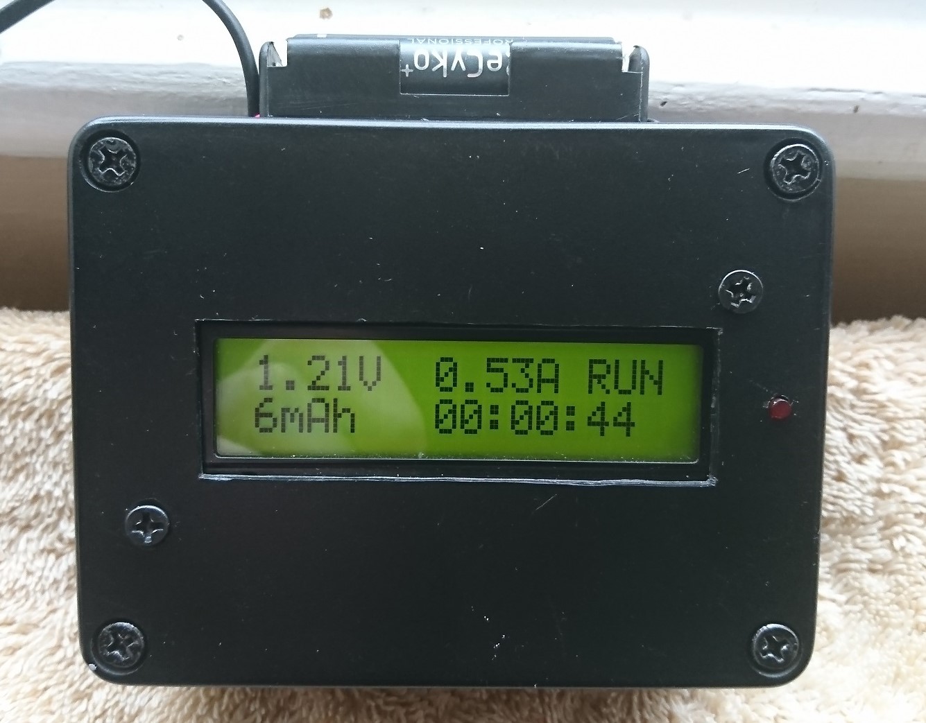 I’ve improved the display layout and included an elapsed time indicator as the tester’s ability to accurately measure the mAh rating of the battery is just not possible with the design. What we are really interested in is the length of time the battery will last for with a given load. Unless you use a constant current load or add the ability to measure the voltage drop across the load resistor and factor this into your formula for calculating the capacity it just won’t produce accurate results. I did originally intend to make a 12V SLA tester version of this which I eventually may do but I will release the code as-is for example purposes. All information is on the project page if you want to check it out.
Arduino based water pump timer using a 240×64 pixel GLCD
Another project I made using old parts that wouldn’t have been used for anything else. This time I used a GLCD for a water timer (OTT yeah I know) but rather than throw out unfinished projects from years ago it is better to repurpose them.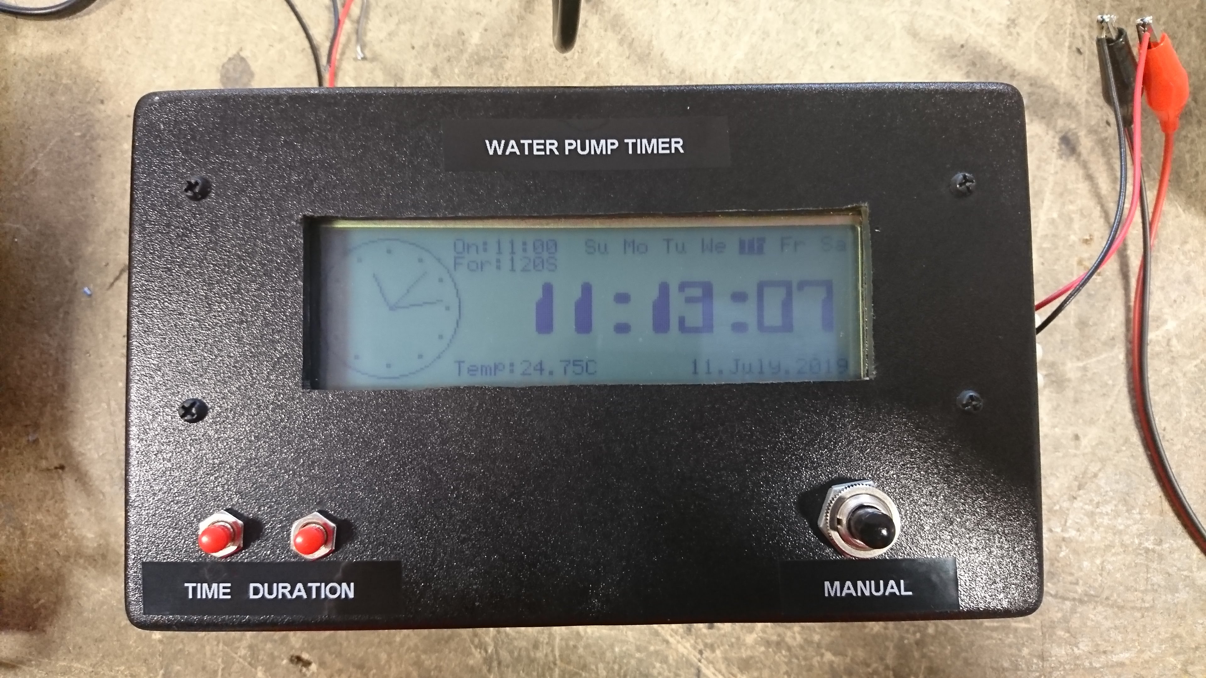
This timer is fairly simple as precision timing is not required for watering a garden. Two switches select the hour at which the pump turns on and the second for the duration required. It is ‘on’ the hour so if you select 11 the pump turns on at 11:00 and runs for up to 360 seconds depending on the values selected. Data is stored in EEPROM so that is not lost if there is a power failure. I’ve also added a few lines of code that turns the pump on again after 8 hours but this can be taken out if needed. A manual override switch completes the front panel so you can water manually on those exceptionally dry days without having to adjust the timer. It’s all a bit too complex for a simple task but I was fed up of those cheap timers that are either rubbish or just go faulty within a year. This could be installed in a garage, cellar or outbuilding with a long cable to the pump to minimise failure due to the weather. The display looks cool too. 🙂