A few weeks ago i decided it was time I got rid of some old shite I’ve been keeping for years. I also decided to make this blog and some of my early electronics projects I have featured on this site. Not that they are any use to me nowadays but I want to keep them well, you know just because. The historical and test equipment pages will fill you in on this.
Some stuff was worth improving and refurbishing. 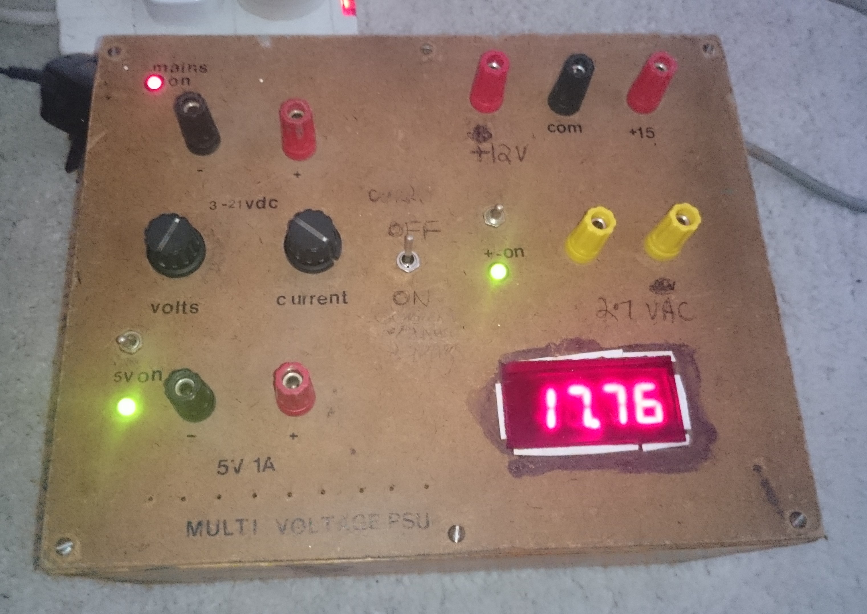 Take this bench PSU I made around 25 years ago which was the most useful thing I made as in it had a purpose and was used often. Well actually I made two bench power supplies back then. The original wooden cased model was lacking in voltage and current so I had made another using a basic regulator with a couple of 2N2055 series pass transistors stuffed into a BBC Micro external HDD case. As all parts were salvaged from scrap save a few knobs and switches I didn’t have much flexibility with the design.
I decided to scrap the latter salvaging the transformer and throwing away the rest as it looked decidedly dodgy and a shock hazard. I didn’t want to trust it. 😉
The first project was in a wooden case which later had a voltmeter fitted so I decided to re-work the power supply boards and fit the transformer from the higher current version. There’s no before photos but I’ve taken some photos of the internals and the revised front panel. Hastily written with pencil I might add 🙂 where’s that Dymo machine?
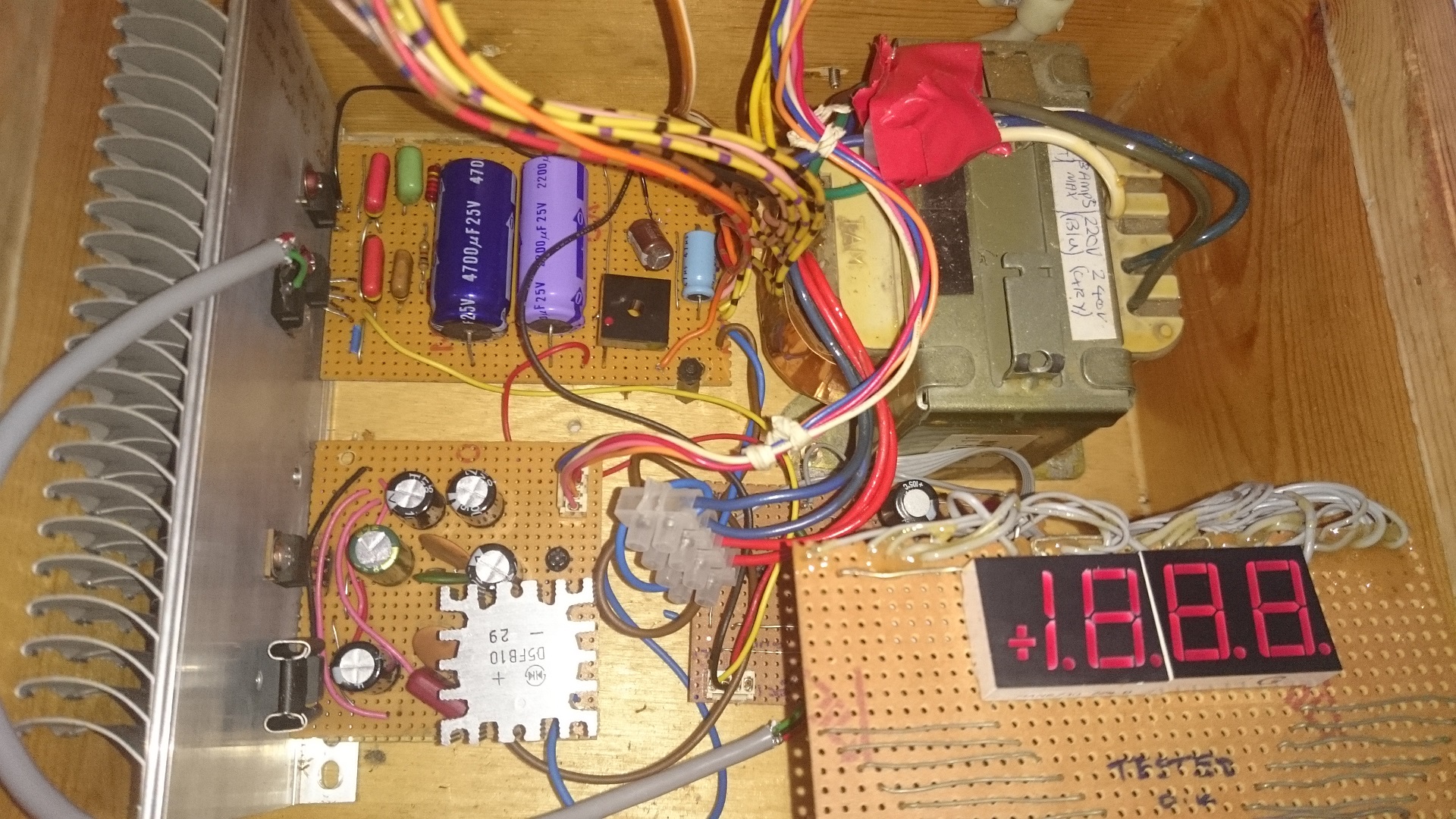 Here’s the internal view. I fitted a larger heatsink and rotated the PCB’s by 90 degrees. The back PCB is the original supplying which was 3-21v at 1A now modified because of the bigger transformer to 3-20V at 2A. I also fitted some new capacitors as the others were 40 years old. This produced much more heat hence the larger heatsink. It still gets stupidly hot though when supplying low voltages at high current as it is having to drop 20V down to 3.3V; that excess energy has to go somewhere! The front PCB is a modified version of the original where I just really changed the regulator IC’s and changed the PCB layout. I also renewed the 40+ year old capacitors which were originally salvaged from old tellies. There’s another PCB under the display containing the DVM chip.
The transformer itself was salvaged from a Sony SL-C6 Betamax video recorder as is the heatsink and bridge rectifier. I still have the service manual for the SL-C6 video recorder so looking at that I found that the transformer has two 16V secondaries rated at 4 amps plus another secondary supplying 2.4V and 20V at lower currents. The 2.4V windings I fed out to the front panel as they would be useful for a filament supply for VFD’s. The 20V tap I left disconnected and insulated as this isn’t required. One 16V secondary I used to power the original board which supplies 3-20V at 2A maximum current and also 5V at 1A. Total draw at full load would be 3A – well within the spec of the transformer. The second 16V winding feeds the 12V and 15V regulators rated at 1A each. The rectified 16V AC gives around 22V no load but drops to around 18.5V when loaded so there’s enough for the 15V regulator to work with for good regulation.
This thing still has it’s uses but I decided to replace it with a microprocessor controlled Tenma bench PSU that can accurately set voltage and current outputs. Thing is back when I made this lab gear was very expensive and hobbyists had no option to make their own gear. Things are very different now.
At the end of this clear out I didn’t throw away much. Guess some of things I made have sentimental value? I don’t know. Maybe I just like hoarding junk. I need to be careful not to repeat this cycle as I’ve found the wonder of the Arduino. Here comes several years making more pointless crap again..